Thx for that link! Seems like they had problems with recreating the HRTF curve with passive mods. Seems to me that it could work with some effort and DSP.
measurements on SLIM 8
Yesterday I received 4 SLIM8 units, and I made some rough initial measurements with a (calibrated) UMIK and REW.
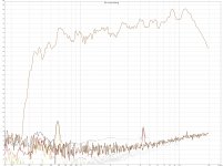
Drivers were suspended by wire, no baffle was used. Mic a 1m distance, only did on-axis measurements (for the moment). Signal ran through a MiniDSP 2x4 which was used to put a low shelving filter with 10dB gain at 400Hz, as well as a 48dB LR also at 400Hz. Furthermore I put 80uF of capacitance in series with the drivers (protection). Same volume settings for all units (but I did not measure actual voltage applied to drivers). Gating set in REW with 7ms in left window, 0 ms window ref time and 9ms right window.
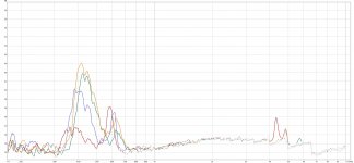
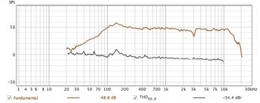
The first picture shows the response and distortion for a single unit. The second and third picture are the overlay of respecitvely the FR and distortion of all 4 units.
I was hoping to be able to make a line array to be used from 400Hz onwards, but I do not think this is a wise idea...
Yesterday I received 4 SLIM8 units, and I made some rough initial measurements with a (calibrated) UMIK and REW.
Drivers were suspended by wire, no baffle was used. Mic a 1m distance, only did on-axis measurements (for the moment). Signal ran through a MiniDSP 2x4 which was used to put a low shelving filter with 10dB gain at 400Hz, as well as a 48dB LR also at 400Hz. Furthermore I put 80uF of capacitance in series with the drivers (protection). Same volume settings for all units (but I did not measure actual voltage applied to drivers). Gating set in REW with 7ms in left window, 0 ms window ref time and 9ms right window.
The first picture shows the response and distortion for a single unit. The second and third picture are the overlay of respecitvely the FR and distortion of all 4 units.
I was hoping to be able to make a line array to be used from 400Hz onwards, but I do not think this is a wise idea...
Attachments

Thank you very much for the measurments...so not asgood as the Neo10 that was usable from something 400 hz...
You are welcome.
The NEO10 and Slim8 are very different, not only pricewise. The NEO10 is twice as wide, that gives it an advantage in the low extension (dipole peak of NEO10 is at half frequency of Slim 8) while worse in the HF. I did not do off axis measurements on the SLIM 8 yet, but I expect that this driver will not need an additional tweeter (the NEO10 does). So I would not say "it is not as good", because it is a different driver with a different operation range
My wish for 400Hz operation was probably more wishful thinking. The idea is that the large number of drivers in the line array would lower the required SPL (and therefore distortion) per driver, but I think that even that is not possible.
I will do more measurements know they are there 🙂
I did not do off axis measurements on the SLIM 8 yet, but I expect that this driver will not need an additional tweeter (the NEO10 does).
If I am reading your plot correctly, the frequency response is dropping like a rock above 12kHz. This makes it a tweeter only for the hearing impaired... Off axis will likely be worse than that (more attenuation, and starting lower in frequency) because of beaming.
Hi Charlie,
I see your point and I do agree that it may not be good as tweeter based on these curves. A pity that another driver would have to be added for about half an octave.
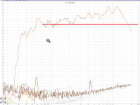
To obtain the above curves I did the shelving low pass with MiniDSP. Looking at these curves I would say this driver could be used from about 800Hz upwards. Currently I have a gain of about 10dB at 800Hz due to dipole cancelation, so instead of positive gain at the low end I thought about attenuating the HF up to about 12k. Ie, cut off everything above the red line.
If that is doable and how it sounds I have to find out.
Erik
I see your point and I do agree that it may not be good as tweeter based on these curves. A pity that another driver would have to be added for about half an octave.
To obtain the above curves I did the shelving low pass with MiniDSP. Looking at these curves I would say this driver could be used from about 800Hz upwards. Currently I have a gain of about 10dB at 800Hz due to dipole cancelation, so instead of positive gain at the low end I thought about attenuating the HF up to about 12k. Ie, cut off everything above the red line.
If that is doable and how it sounds I have to find out.
Erik
Attachments
Hi Charlie,
I see your point and I do agree that it may not be good as tweeter based on these curves. A pity that another driver would have to be added for about half an octave.
To obtain the above curves I did the shelving low pass with MiniDSP. Looking at these curves I would say this driver could be used from about 800Hz upwards. Currently I have a gain of about 10dB at 800Hz due to dipole cancelation, so instead of positive gain at the low end I thought about attenuating the HF up to about 12k. Ie, cut off everything above the red line.
If that is doable and how it sounds I have to find out.
Erik
Although it depends on the input sensitivity of your amps and the output voltage drive capability of the miniDSP, from what I recall it is better to EQ using attenuation than to boost so that you do not overdrive the DAC stage. That might happen with a 10dB boost, for example. You can add back a bit of gain using flat gain later to balance out the gain between channels.
There seems to be a problem at about 4.3 kHz, a peak in the distorsion.
Which harmonic is the red trace? Problem may be higher in frequency.
There seems to be a problem at about 4.3 kHz, a peak in the distorsion.
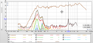
Yes, at the low SPL levels shown here only my unit 1 has this. Unit 4 was tested at higher SPL levels, and it looks like in the attachment. Again, the distortion peak at almost 5k.
As written in the previous post, I will probably attenuate the HF anyway, so this distortion will be lowered.
There is quite some tinkering regarding this 🙂
Attachments
Which harmonic is the red trace? Problem may be higher in frequency.
In post 62 the curves are the THD for each of the 4 drivers. IIRC the peaks at around 4k are 2nd order, as shown in post 70 for driver 4.
Last edited:
Yes, that looks like rather big membrane tension differences
But considering the price one could have feared bigger individual deviations than this. Depending on the actual input level, distortion is not horrific nor great.
For the projects I have going on, the two peaks and relatively early drop off, as well as the tension and general slope makes it suboptimal.
Which does not mean that it's not a useful or manageable design in general 🙂
Thanks a lot Erik!
Last edited:

Yes, at the low SPL levels shown here only my unit 1 has this. Unit 4 was tested at higher SPL levels, and it looks like in the attachment. Again, the distortion peak at almost 5k.
As written in the previous post, I will probably attenuate the HF anyway, so this distortion will be lowered.
There is quite some tinkering regarding this 🙂
Nice!
Are those SPL levels calibrated @1m?
And that 5 khz distortion peak is pure second harmonic so I wouldn't worry that much. Especially since it is in the single digit %.
It looks like running the slim ones nude and covering 400 hz and upwards is probably asking too much. The wide should be able to do just that as measured over at audiocircle GRS-3 vs Neo 3. The wide variant seems to perform @ 500 hz how the slim performs @ 800 hz. Should be a worse tweeter though.
I ordered 2 slim for myself aswell, I want to test how a 20-30cm wide wool baffle will impact the 0-90 response. In my previous experiments lossy wool baffles have worked very well for dipoles to bump the low frequency response without adding a sharp dipole peak. I also want to try to see if my idea of how to arrange the midwoofers will play nice with in the worst case a 800 hz crossover.
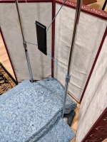
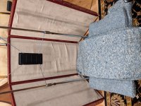
Still pouring over the data, but here are few photos of the testing rig. I'll try to get some curves up tomorrow night.
The background noise level in the studio was measured at about 40dB. Testing occurred at 1ft and I set the first driver, an original BG Neo-10, at 95dB at 1KHz and didn't touch mic gain or playback level after that.
Do you guys want me to include the full REW file instead of posting endless graphs?
Greg
Attachments


Could you measure in a baffle Greg and Eric? For those of us who might use them in an enclosure. Thanks for the plots and hard work.
How about a few graphs for discussion and the file for deeper dives? Also any general impressions or conclusions so far?
...Do you guys want me to include the full REW file instead of posting endless graphs?
Greg
I would like to see the graphs but I'm sure many others would like the files. If you can post both it would be great, if not too much work on your end.
Here's a Dayton-Wright ESL cell, 45 yrs old. THD looks about -54dB at 1kHz, about 130 Hz high-pass, on June 29, 2019.
B.
B.
Attachments
Last edited:
- Home
- Loudspeakers
- Planars & Exotics
- New planar drivers at Parts Express