I know it has been briefly discussed somewhere but I can't find the differents posts.
If someone has the posts numbers I 'd greatly appreciate.
I am talking about adding a remote control for the volume.
Thanks
If someone has the posts numbers I 'd greatly appreciate.
I am talking about adding a remote control for the volume.
Thanks
I see two pads on the diyaudio board labled "F3". What does this refer to? I bought a 6P1 Carrier PCB from nutube.us (a Pete Millett design?) so I could mount the NuTube and carrier board on my front panel (to view the glowing tube though a machined panel opening), and then run wires back to the diyaudio board. From the schematic that comes with the carrier board, it looks like this carrier board connects these "F3" points to breakout pads labeled "F2" and "FC" (filament 2, and filament common). Is the "F3" designation on the diyaudio board a mis-label? Sorry if I'm just being dense here. Not trying to be difficult.
to zapped #5264
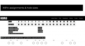
F3 = Filament 3 (right) = Pin17 of the NUTUBE.
Sorry, I don't know the pcb from Pete Millet.
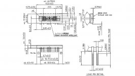
I have added parts of the datasheet of the NUTUBE.
But you only have to measure. Pin 1 from the Pete Millet board to Pin1 of the
Nelson Pass pcb; Pin 2 to Pin 2 and so on.
Check datasheet (pics below) - there are a few NP (no pin!)
I hope this helps!
Greets
Dirk
F3 = Filament 3 (right) = Pin17 of the NUTUBE.
Sorry, I don't know the pcb from Pete Millet.
I have added parts of the datasheet of the NUTUBE.
But you only have to measure. Pin 1 from the Pete Millet board to Pin1 of the
Nelson Pass pcb; Pin 2 to Pin 2 and so on.
Check datasheet (pics below) - there are a few NP (no pin!)
I hope this helps!
Greets
Dirk
Attachments

Pass DIY Addict
Joined 2000
Paid Member
The B1K build guide, produced by 6L6, is now up:
B1 with Korg Nutube - diyAudio Guides
Many thanks to 6L6 for his typically wonderful work on this!
Seconded! Have not built mine yet but will use this extensively when I do!
Riki
Build Guide Images Missing
I just printed the Build Guide. Starting with Step 7, all the images failed to print. Anyone have any thoughts why this would be?
I just printed the Build Guide. Starting with Step 7, all the images failed to print. Anyone have any thoughts why this would be?
It’s an enormous file if you just tried to print it. You probably drowned your printer buffer.
Thanks, I thought about that. I tried printing one page and the images were still missing. Steps 3-6 printed with the images but no images after that, even printing the pages individually.
3 minutes ago I downloaded the guide as .pdf and then saved the .pdf file on my computer. When I open it with my Acrobat Reader, I can print pages just fine. For a test I successfully printed page 12 of 32: Step 19 and Step 20
Maybe you can extract a set of pages by printing them (like, marks selection) to pdf instead of to the printer, and then print that?
Im currently assembling my B1 kit. In anticipation of potential microphonic issues, I'm considering several options to quell those problems. I have a separate small PCB carrier board to mount the NuTube on and will mount the tube on this board separately from the main PCB connected by flexible wiring. I'll damp between the tube and small PCB (maybe with Dynamat, maybe something else). The Dynamat appears to be about ⅛ inch thick and I am considering lining the entire inside of the chassis. Alternatively, i may just line the top and bottom panels. I have no idea how hot it gets inside the chassis and it has no vent holes. Does anyone know if using the Dynamat would trap too much heat inside to be feasible? Any other thoughts would be highly appreciated.
Pass DIY Addict
Joined 2000
Paid Member
There are no heat issues at all with the B1 Korg kit. Feel free to cover the inside with whatever damping materials you'd like.
I installed a DC regulator inside my chassis, with the mosfets attached to the chassis floor. This makes the bottom of the chassis mildly warm, about body temp. Still plenty safe to install damping material in this case. Vent holes are not necessary at all.
I installed a DC regulator inside my chassis, with the mosfets attached to the chassis floor. This makes the bottom of the chassis mildly warm, about body temp. Still plenty safe to install damping material in this case. Vent holes are not necessary at all.
Im currently assembling my B1 kit. In anticipation of potential microphonic issues, I'm considering several options to quell those problems. I have a separate small PCB carrier board to mount the NuTube on and will mount the tube on this board separately from the main PCB connected by flexible wiring. I'll damp between the tube and small PCB (maybe with Dynamat, maybe something else). The Dynamat appears to be about ⅛ inch thick and I am considering lining the entire inside of the chassis. Alternatively, i may just line the top and bottom panels. I have no idea how hot it gets inside the chassis and it has no vent holes. Does anyone know if using the Dynamat would trap too much heat inside to be feasible? Any other thoughts would be highly appreciated.
You could try mounting on daughter pcb and clamp it with thick acrylic
My friend just glued it with viscoelastic tape no issue as well. But he did mention the rigidity of the casing matters . He machinesd a nice thick top cover for the casing
US $1.93 16%OFF | 2020 Transparent Velcro Nano Tape Washable and Reusable Double-sided Adhesive Adhesive Universal Hook Tape for Furniture
2020 Transparent Velcro Nano Tape Washable and Reusable Double sided Adhesive Adhesive Universal Hook Tape for Furniture|Hooks & Rails| - AliExpress
2020 Transparent Velcro Nano Tape Washable and Reusable Double sided Adhesive Adhesive Universal Hook Tape for Furniture|Hooks & Rails| - AliExpress
Pass DIY Addict
Joined 2000
Paid Member
Using rubber mounts between the chassis and the PCB reduced my NuTube ringing by 15dB. A year ago, these were $2.20/set of 4. The price has gone up since, but still a good buy:
M3 Rubber Shock Absorber Damping Anti-Vibration Holder for F3 F4 Kiss FC M2Y5 | eBay
If the link dies, just search on "M3 Rubber Shock Absorber" or use the word "Anti-Vibration" instead. You'll find tons of them.
M3 Rubber Shock Absorber Damping Anti-Vibration Holder for F3 F4 Kiss FC M2Y5 | eBay
If the link dies, just search on "M3 Rubber Shock Absorber" or use the word "Anti-Vibration" instead. You'll find tons of them.
- Home
- Amplifiers
- Pass Labs
- B1 with Korg Triode