PCB toner transfer files are attached 🙂 may be someone will make to sing ....
Regards ,Alex
Hi Alex and Damir,
Do you have a BOM for the design?
Also, what is the latest schematic that goes with Alex's PCB?
Thank You.
Last edited:
This is schematic from post #91 https://www.diyaudio.com/forums/solid-state/253039-unique-cfa-120-230w-amp-10.html#post4113328
I don't have BOM as I never built this amp (I should in the future 😱), you should use the values from the schematic, I am sorry for inconvenient.
Some people built this amp or variant of it(could be found in this thread) and you can try to contact them.
BR Damir
I don't have BOM as I never built this amp (I should in the future 😱), you should use the values from the schematic, I am sorry for inconvenient.
Some people built this amp or variant of it(could be found in this thread) and you can try to contact them.
BR Damir
Last edited by a moderator:
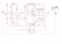
Hi Damir. I am not very good with LTspice and wanted to sim the 200W amp in m*ltisim. I have some queries that maybe you can help me with. Schematic and zipped sim attached. I included a PDF schematic as well, as it is easier to read.
Please bear with me, although I have built several nice amps, I am not an electronics whiz 😀
- Can you let me know if I have connected the Servo correctly.
- Should R10/39 be 3k6.
- Should C9/10 be 220p.
- Should C14 have a symmetrical Cap going to the Collector of Q8.
- Have I connected the Signal Grounds correctly.
- I seem to have to use a lot of input signal (3Vp at 1 KHz) to get 200W into 8 Ohm's; have I made an obvious mistake in the schematic.
- Lastly. Can the amp drive 4 or 6 Ohm speakers.
Thanks for all the effort.
Attachments
Last edited:
Great. Thank you Damir.
Ref the Signal Grounds, I followed the Schematic in your post #36.
I'll make the changes to correct my mistakes.
Cheers.
Ref the Signal Grounds, I followed the Schematic in your post #36.
I'll make the changes to correct my mistakes.
Cheers.
Attachments

Last edited:
Hi Damir. I am not very good with LTspice and wanted to sim the 200W amp in m*ltisim. I have some queries that maybe you can help me with. Schematic and zipped sim attached. I included a PDF schematic as well, as it is easier to read.
Please bear with me, although I have built several nice amps, I am not an electronics whiz 😀
- I seem to have to use a lot of input signal (3Vp at 1 KHz) to get 200W into 8 Ohm's; have I made an obvious mistake in the schematic.
Just realised Q21, Q22, Q2. All Collector and Emitters wired in reverse; wonder what else I've gotten wrong!!!😱
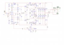
Seems to work now. Signal Grounds placed as described by Damir. m*ltisim file attached. Sim models updated. Hope it is good now.
Because there is no BOM here are some important data:
Some resistors should have higher dissipation values, others just 0.6W/0.5W 1% metalfilm.
R10/R39 2W metaloxid 5%
R9 2W 1% metalfilm
R37 8W or more metalfilm 1% - I use parallel-serial combination of 2W resistors
output transistors emitter resistors good low impedance 5W
Capacitors used in compensation could be ceramic NP0/C0G, silver mica or polystyrene
Input cap if you use it good polypropylene
 New thread on Mexmike amp here:
 Request
Hi mr alex. Its imposible to you that share graber file?
Your design is number1
I have check again ,found only one bad connection ,corrected now ,and I think are no more errors IMHO 🙂 so we can move ahead.....
Alex
Hi mr alex. Its imposible to you that share graber file?
Your design is number1
- Home
- Amplifiers
- Solid State
- Unique CFA 120/230W amp