Thank you very much
Is it possible for you to inject a ripple signal at 1 -10
And 20khz and measure again?
Is it possible for you to inject a ripple signal at 1 -10
And 20khz and measure again?
The phono preamp is most sensible in the low range, 20-100hz. Output amplitude drops the higher in frequency I go.
I will try to build a LNA and maybe try more measurements.
I will try to build a LNA and maybe try more measurements.
Last edited:
I'm thinking of this amplifier that was presented here by user Calvin, designed by Douglas Self:
Simple 60dB discrete low noise amplifier (lna)
There's the article describing it, and complete LTSpice sim with models, a few posts down. I think it could be made with ne5534/tl071 easily tho I do have some opa827. It can be made for 60dB max gain with selectable gain for x10, x20, x50, x100, x200 and x1000. Parts should be cheap. Input cap could be lowered to 47uF for film caps, dunno if they fit.
I'm trying to make a 10cm X 10cm board made, and I think I can cram this amp with +- dienoiser circuits (with clc filter), also a version of the board I diyed and a few versions for ultra small smd add-ons for lm317/lm337 dienoiser/denoiser, one with electro tht caps, one with tantalum smd. I'll need to cut them out myself but I have some silkscreen lines to help me out.
Search for threads started by diyAudio member SGK . If I remember correctly, he managed to find people who had extra copies of the original PCB. Maybe one of them still does (?!!). If so that would be far easier than laying out a new board!
I have to make a pcb anyway for the smd add-ons, so I can cram it in the Magni, can't diy as traces are too small. Since I'm doing a two layer and 10x10 is 2$ I might as well put some other stuff on it.
Would be useful to see the original design tho, to get inspired.
I see that swapping the NE5534 with OPA827 or LM4562 isn't working in the sim. Need to understand what's happening. NE5534 draws 20mA total in the design, for x1000 things complicate a bit, max input signal is way lower, and it draws less current. It's doable just that I want to understand the circuit a bit better.
I think you are referring to a different circuit? This one has only 3x 2n4403, no FETs. It's a MC preamplifier.


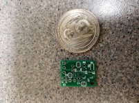
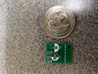
I received the SMD boards designed by Trileru. I'll have to order a few parts, I'll let you know how they work.
I am using these in a Hafler DH-110 preamplifier. It has a typical LM317/337 regulater with no added parts. It is quiet already, but if I can lower the floor 30dB, why not. I already replaced all the electrolytics and cleaned the switches.
Will make a nice garage preamp!
It is quiet already, but if I can lower the floor 30dB, why not.
The pcb has 2 transistors so it must be a Die-noiser or a No-noiser. As far as I know, only 1 transistor original version is suitable for retro-fitting. Also, two transistor versions can do more than -30dB. Am I wrong?
What voltage rating does C4 need to be? 16V is very common, but I know my Power supply is outputting 23volts. Does C4 see all that voltage?
The input cap sees all of the output voltage and the collector one sees the OP minus a few volts.What voltage rating does C4 need to be? 16V is very common, but I know my Power supply is outputting 23volts. Does C4 see all that voltage?
Probably a bit over 16V with a 23V out.
If the bias resistor is increased, it is possible to go under 16V.
Large value ceramic caps have a huge voltage coefficient, much higher than Ecaps. I don't recommend using them there
Would a surface mount ceramic cap work for C4?
C4 is the 22nF cap from the compensation network. I paralleled two 10nF 0805 ones on the diy board as I didn't have the 22nF value at hand.
0805 22nF caps should be easy to find in min 50V rating.
R7 is also from the comp network and you could try to solder the jumper to bypass it but I'm not sure of the stability. Maybe Elvee can chime in? Is that resistor needed for the Denoiser or Dienoiser?
edit: You could try to connect the gnd/reg_output connections close to either the lm317 output cap either close to the point of load. See what works best if you can measure the results. I'd try with the Dienoiser version at first, because it offers lower noise and a tighter voltage swing at startup.

edit: You could try to connect the gnd/reg_output connections close to either the lm317 output cap either close to the point of load. See what works best if you can measure the results. I'd try with the Dienoiser version at first, because it offers lower noise and a tighter voltage swing at startup.

Last edited:
My plan is to use the denoiser, less parts, more stable and the Hafler is already pretty quiet. From Elvee's initial DeNoiser diagram I was going to order 3.3nF C4's. C3, R2 and C5 are already on my Hafler board. The Hafler board had 22uF for C3, so I'm swapping in 470uF for C3 on the board and using the 22uF for C2 on the DeNoiser.
Where did C3 change from 3.3nF to 22nF for the DeNoiser?
Where did C3 change from 3.3nF to 22nF for the DeNoiser?
R2 and C5 are for the 78xx reg types, not to be used for the lm3x7 types.
C3 is wired to ground in normal lm3x7 circuits. You need to take it out of the normal circuit and tap the adj pin that you'll then have access to. I don't think you can use it on the initial circuit.
Elvee put 10nF for C4(C2) in his schematic when he made a recap of the circuits, and I see Diego used 22nF for his Dienoiser. I think 10nF-22nF should do without problems.


Last edited:
You could try to take out the ground leg of the ADJ cap on the initial circuit and wire it to the denoiser board on the ADJ connection, but you'll need to bridge C3 on the denoiser add-on board. But I'd just add it to the denoiser board. I think the board could fit a 8mm diameter one and would just barely touch the 22uF one.
- Home
- Amplifiers
- Power Supplies
- D-Noizator: a magic active noise canceller to retrofit & upgrade any 317-based VReg
