Hello everyone! I've recently come in the possession of an old Little Dot II++, the problem is that there is an audible hum (around 50 Hz, I'm in Europe so 50 Hz AC here) coming from the transformer, this wouldn't be much of a problem since I'll be wearing headphones when I'm using it if not for the fact that it is also clearly picked up by the amps and is reproduced (and I'd say it's also pretty loud) by the headphones. Things I already tried:
- Changing tubes, both power tubes and signal tubes.
- Changing cables.
- Trying different power outlets.
Unfortunately I don't know anything about electronics so I haven't been able to test anything else. As you can imagine since I'm posting here none of this helped, there is still a clear backgroud humming. If anyone could help me I'd be really glad!
Last edited:
Very compact design its no wonder with the power supply inches away from the audio section that any fault in the PU would transfer itself to the rest of the circuit .
As this could be faulty capacitors or rectifiers etc which would involve replacement and you have no technical experience I would be loathe to try and talk you through tests and replacements as its very easy in such a compact design to make mistakes and you would ,of course , need to buy equipment for the work.
Maybe somebody here has one with the same fault and cured it ?
Thank you for your answer. While I don't have any experience I have a good friend that does that is willing to help me, I halso have a soldering iron and a tester if those could be useful.
Logically the first step would be to replace the large capacitors , if you have a capacitance checker you could use that to check each one after unsoldering the connections to it.
I only have a multimeter right now with me, it's my understading that it can't be used to check the capacitors (again, sorry I have little knowledge of elecronics), I'll see if I can find the one needed to check them.
I've attached photos of the board, I apologize for the poor lighting, I'll try to get better photos tomorrow when the sun is out. Also the cables are fixed so it's kinda hard to get a good photo of the underside, this is also going to be a problem when soldering I guess but we'll work something out.
I've attached photos of the board, I apologize for the poor lighting, I'll try to get better photos tomorrow when the sun is out. Also the cables are fixed so it's kinda hard to get a good photo of the underside, this is also going to be a problem when soldering I guess but we'll work something out.
Attachments

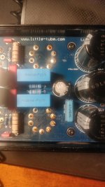
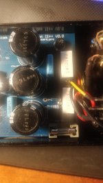
I would check those three black power supply capacitors first , its probably the bad light but the middle one seems to have a slight bulge at the top ?
Then the two at the other end .
Then the two at the other end .
The capacitor seems fine, I'll attach photos tomorrow with better lighting. Meanwhile I bought a cheap LCR meter that my friend says should do the job, I will test the capacitors when I get it.
You should check for sure if the hum is from the unit itself by removing the cables and shorting the inputs .
But if the headphones are very sensitive , from my experience , only simple RC filters , in this case made with those 3 capacitors , are not enough for removing all the ripple ...
But if the headphones are very sensitive , from my experience , only simple RC filters , in this case made with those 3 capacitors , are not enough for removing all the ripple ...
Right now I'm using a pair of Beyerdynamic Custom Studio 80 Ohms, I'm waiting on a RMA on a pair of DT 1990 Pro 250 Ohms.
Things that are important but I forgot to mention: the hum is present even when there are no RCAs connected (that means it should be the unit, right?) and the hum wasn't always present, it wasn't there when I first got the amp a couple of months ago, I was waiting on new and better tubes to come in before actually using it so I haven't used it in a while. New tubes came in a couple of days ago and that's when I noticed the problem, switching back to the old tubes didn't solve the problem.
Things that are important but I forgot to mention: the hum is present even when there are no RCAs connected (that means it should be the unit, right?) and the hum wasn't always present, it wasn't there when I first got the amp a couple of months ago, I was waiting on new and better tubes to come in before actually using it so I haven't used it in a while. New tubes came in a couple of days ago and that's when I noticed the problem, switching back to the old tubes didn't solve the problem.
That was my guess too Depanatoru ,probably very simple filtering not even to reduce the ripple enough, old electrolytics decrease in value over time .
Its unfortunate in this compact design that a capacitance multiplier could not be added.
Its unfortunate in this compact design that a capacitance multiplier could not be added.
Arci966,
If you do not know:
Open Shade on a sunny day will provide good lighting for your amplifier pictures.
Or else, a day with clouds everywhere.
Direct Sunlight on the amp, is not good lighting for your pictures.
Seeing your amp, makes me thankful that all my amplifiers do not have PCBs.
I hate unsoldering parts from PCBs. I have destroyed many Pads that the parts connected to.
You may have to unsolder the capacitors to be able to measure the capacitance.
Depends on the rest of the in-circuit parts connected to the capacitors.
Good luck on pushing the hum levels down.
Ground loops, especially when the power supply loops are extended to the other circuitry will make for lots of hum.
All power supply grounds should be local loops before the last cap negative is connected to the other amp grounds.
Unfortunately, any ground loops that are on the PCB are already fixed, and near impossible to fix.
It is hard for me to get hum levels down, but most of my amplifiers have less than 100uV hum.
But even that is probably not low enough for sensitive headphones.
I use loudspeakers.
One possible fix for you is to build an attenuator between the amplifier output, and your headphones, and then turn the volume up.
That will make the Music to Hum ratio more like what you want to hear.
It depends on how much power your headphones require, and how much the amplifier output is (before it distorts).
Last edited:
Thank you again for your answers. The hum is not that strong, when playing music I can notice it only in the quieter sections, it's just that I wanted to use the amp hooked up to my PC and the hum will drive me mad when I'm just browsing reddit/doing stuff without music on.
Since the hum started when you made the change of tubes, then it could well be that something was disturbed at that time, causing the hum.
Are the tubes identical? Are the delicate connections to and from the RCA plugs OK? Did all the grounding connections get put back together OK when reassembling it?
Speaking as an IT person, it is usually the most recent improvement that causes an issue ;-)
Are the tubes identical? Are the delicate connections to and from the RCA plugs OK? Did all the grounding connections get put back together OK when reassembling it?
Speaking as an IT person, it is usually the most recent improvement that causes an issue ;-)
Thank you for your answer. While I don't have any experience I have a good friend that does that is willing to help me, I also have a soldering iron and a tester if those could be useful.
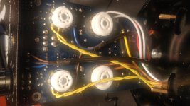
Have your friend check the rectifier bridge. That is the little round thing on the upper right hand corner of the PCB in picture #3. That is the weakest link of the Little Dot MK2 power circuit. It is possible that the low-ish 60 ohms load combined with a strong tube broke it. Note: It is ~200V there and the capacitors will hold charge for a little while even if the power is off and there is a 150K path to ground, be-careful. There are enough juice to cause harm.
Are the tubes identical? Are the delicate connections to and from the RCA plugs OK? Did all the grounding connections get put back together OK when reassembling it?
The signal tubes are different but I got them as soon as I got the amp and they worked fine with the old power tubes. The power tubes should be the same kind of tubes but the new ones are russian (Svetlana 6C19N) while the old ones were chinese (6C19-J). Connections to the RCA plugs seems fine, I did not disconnect any grounding connection when disassembling the unit, but I still checked and every connection seems fine.
Have your friend check the rectifier bridge.
I performed a quick check following a youtube video I found, I did not desolder it and checked on circuit (which I'm reading it's not optimal but it can be fine), all the diodes show a 0.5 (more or less) Voltage drop and no voltage when reversing the two probes so, at least according to the video, they should be fine. Again I'm literally learning all of this right now since seeing my friend could not be so easy right now with the whole COVID situation and if it's something simple I can do it (and also learn something in the process).
It looked quite toasted under the power tube sockets - could you have unwittingly cracked a trace when switching tubes? How good are those solder joints? My thinking is that it happened after manipulating the PCB, so must relate to flexing or assembly. The alternative would be damage caused by incorreect tubes, but that has been discounted.
There is always what a friend of mine called the 'f***-it factor' where something totally unrelated goes wrong at the same time, but normally an issue after a change is linked to the change.
There is always what a friend of mine called the 'f***-it factor' where something totally unrelated goes wrong at the same time, but normally an issue after a change is linked to the change.
Yeah it doesn't look good under there, but it mainly looks like flux residue. I agree it's probably due to the tube swap, let's say i broke off a trace, wouldn't that mean the tube shouldn't work at all?
I have broken a trace before, trying to prise free old electrolytics off an old PCB. It is not terminal, but you need to see where it could be damaged.
Another option could be the tracking of the heater wires. They are the twisted pair on the top side of the PCB - maybe the way they were routed has been changed in reassembly? That could cause some interference.
It is an interesting choice of preamp tube - an EF92, which is a variable-mu tube, and not one that I would have thought would be useful.
Thanks for bring that up OldHector used those tubes in my communications receivers -VM--= distortion does he know they are specially shaped to VARY with signal input --a must with RF equipment to stop overloading ?
Whats the designer thinking of -- did he spend time on head-fi -tube rolling section ?
Whats the designer thinking of -- did he spend time on head-fi -tube rolling section ?
- Home
- Amplifiers
- Tubes / Valves
- Little Dot II++ humming.