Are the voltage heathers the two pins that are connected to the power supply (white, brown and yellow in the photo)? And what's B+? Sorry, but again, I'm not well informed on the matter.
I guess two white, two yellow & two clear brown, B+ surely is dark brown & blue. Please measure with tubes conected.
Do you have a schematic?
Do you have a schematic?
Last edited:
I managed to take a better (I think at least) photo of the back of the board, still no sun here so still bad lighting. Just to confirm, the voltage heater cables are the pair that goes to each tube socket, right? And I would have to measure the voltage going trough while the amp is on, right?
The blue cables are connected to the L channel of the RCA connectors, I should check those? If yes, what should I check?
The blue cables are connected to the L channel of the RCA connectors, I should check those? If yes, what should I check?
Attachments
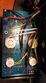
EDIT: Ok I checked the voltages of the heaters, I read 6.3V on the preamp tubes and 6.7V on the power tubes, all four of them are rated for 6.3V, are the 6.7V I'm reading on the power tubes ok? And sadly no, I don't have and I can't find a schematic, the fact that this model has been discontinued 12 years ago doesn't help.
(Sorry for the double post it wouldn't let me edit my last one)
(Sorry for the double post it wouldn't let me edit my last one)
Last edited:
The best solution will be to get off some wire of the secondary power transformer, but also you can try small ohmic value power resistor in series at the secondary between the tx & the heaters.
Ok so, I got the LCR tester, I desoldered the capacitor and tested them, they test as 513 uF, 499 uF and 509 uF, they are rated for 470 uF. I also tested the voltage going trough them and it's at 170V. Are these values fine?
Thank you Merlin for your answers, I re-tested the voltage of the heaters and this time I got 6.3V on the power tubes and 5.7V on the preamp tubes, they are both supposed to be at 6.3V so I don't know if this could be a problem.
Just to be safe I also re-tested the rectifier bridge and all four of the diodes seems fine showing a 0.45 voltage drop only in one direction.
I can't say that it vibrated but the "hum" is clearly audible by ear, not only reproduced by the headphones.
Could you fix using some plastic isolators to damp the vibration? It's a good signal isn't hot. Be sure all copper traces of PCB makes contact between components.
In your original post you said the vibrations came from the transformer ------ tighten up the nuts holding down the lamination's.
Its usually a case of inexpensive transformer design and "cures " include potting it with varnish.
Yes I have fixed this fault in cheaper mains transformers by tightening up the nuts holding the lamination's.
Its usually a case of inexpensive transformer design and "cures " include potting it with varnish.
Yes I have fixed this fault in cheaper mains transformers by tightening up the nuts holding the lamination's.
ok, I've thightened the bolt that keeps the transformer attached to the case of the amp. Today I'm getting a new 9V to power the LCR tester (the one I was using was reading as 7.12V and I don't think that's ideal), just to double check that the condensers are ok. I will then try to resolder them (friend that knows how to solder isn't available, aldready tried one time by myself, didn't go well) and see if the problem is solved.
In the meantime while looking at the board I found 2 jumpers, with a bit of googling I found out that those are a gain settings (a shame no one took the time to scan the manual of this amp back in 2006), right now they are shorted setting the amp to high gain, I'll try with them off and the amp set to low gain, I'm pretty sure that will help increasing the SNR.
In the meantime while looking at the board I found 2 jumpers, with a bit of googling I found out that those are a gain settings (a shame no one took the time to scan the manual of this amp back in 2006), right now they are shorted setting the amp to high gain, I'll try with them off and the amp set to low gain, I'm pretty sure that will help increasing the SNR.
While making the transformer more secure by tightening the bolt(s) attaching it to the case I was meaning the actual lamination's which make up the transformer they must be tight .
Is there no way of tightening them or did tightening the whole transformer to the case work ?
Is there no way of tightening them or did tightening the whole transformer to the case work ?
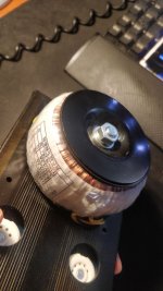
Ah, I dont know, the transformer is a toroid (photo attached) and I can't see any other screws/bolts, should I try detaching it?
EDIT: got the new battery, capacitors test as follows:
200V 470uF:
- 428uF, ESR = 0.13 Ohms, V drop: 0,6%
- 429uF, ESR = 0.14 Ohms, V drop: 0,3%
- 432uF, ESR = 0.13 Ohms, V drop: 0,3%
250V 33uF: 29.53uF, ESR = 0.86 Ohms, V drop: 0,6%
200V 220uF:
- 238uF, ESR = 0.15 Ohms, V drop: 0,5%
- 237uF, ESR = 0.15 Ohms, V drop: 0,5%
Are these values fine?
Attachments
Last edited:
Okay now I know its a toroid then Merlin is quite correct there should be a nylon/rubber composition circular insulated spacer between BOTH the top plate and the bottom plate .
This isn't just for reducing noise but an official approved engineering regulation to stop any chance of the steel plates shorting out the winding's in a case of overheating or damage to the insulation.
I have witnessed this before in a blown transformer --all black/burnt at the shorted point .
This isn't just for reducing noise but an official approved engineering regulation to stop any chance of the steel plates shorting out the winding's in a case of overheating or damage to the insulation.
I have witnessed this before in a blown transformer --all black/burnt at the shorted point .
- Home
- Amplifiers
- Tubes / Valves
- Little Dot II++ humming.