Thanks Francois,
I will open a thread about it, I’m curious too.
I will also propose and simulate some variations.
I will use this page as reference to pick some drivers: Driving hard (Part I) – Bartola(R) Valves
I will open a thread about it, I’m curious too.
I will also propose and simulate some variations.
I will use this page as reference to pick some drivers: Driving hard (Part I) – Bartola(R) Valves
Hi Roberto,
Great idea to start a new thread for design, simulation and building of a EL509 PP UL amp. Personally, I’m very interested in the schematic of the “Final” amp described by Kjeld Pedersen in this diyAudio thread. If you have not seen it already I think you will enjoy reading it too:
Special offer for skilled tube fanatics
Last edited:
Hi evryone,
I need a definitive answer if KT120 tubes can be used with the original pcbs that were produced by bandol83. Also need to know if the Toroidy transformer suggested by bandol83 for the EL34 is also good for the KT120's.
I saw the image in the threads of all the tubes that can be used, but need a definitive answer before I start ordering components.
Thanks for the help,
Myles
I don't understand how a 12AX7 LTP can drive a pair of KT120 tubes in class AB and the local feedback loop. Don't you need more gain and higher gm than what a 12AX7 can give you?
The original Baby Huey uses a 12AX7 to drive a pair of EL84 or 6V6GT. The max peak voltage at the grid of an EL84 will be something like 12 or 13V pk. For a 6V6, figure 15V to 20V pk. EL34, if you run it at lower voltage and higher current might need 25V to 30V peak. For KT120 with a 400V B+ and fixed bias? 40V peak? 45V peak? How can a 12AX7 do that *and* supply the extra swing needed to drive the feedback loop?
My opinion is you want to make an LTP out of something like a pair of EF184 pentodes or something along those lines for big honkin' power tube like KT120.
But I could be wrong. I often am.
--
Kokanee,
some users have installed KT88 with 400 V B+, and tested KT120 too with same voltage and higher current. IIRC Raa load was 6.6 kOhm.
But please have a look at this post: EL34 Baby Huey Amplifier
This could be a good schematic for the EL509 too.
some users have installed KT88 with 400 V B+, and tested KT120 too with same voltage and higher current. IIRC Raa load was 6.6 kOhm.
But please have a look at this post: EL34 Baby Huey Amplifier
This could be a good schematic for the EL509 too.
Thanks for the reference posts. The reason I asked about the KT120's, is that I read in some other thread here, that the KT88's are garbage compared to KT120's (which I took with a grain of salt) and so for a few $ more, use the KT120's. My brain automatically assumed that the KT120's could just be swapped with KT88's in the BH design, as I am a rookie at this stage.
If I was looking at Class A, triode or pentode operation do you recommend just building BH with Marc's direction in the thread, therefore KT88's can be used with the 4.3kohm transformer.
If I was looking at Class A, triode or pentode operation do you recommend just building BH with Marc's direction in the thread, therefore KT88's can be used with the 4.3kohm transformer.
Thanks for the info, Think I will build as per Marc's direction and be quite satisfied. using the recommended transformer and tubes.
I have built with KT88 and the 6.6k transformer. My advice would be to go with a 4.3 or 3.8k transformer. I ordered 6.6 by mistake. Driving these larger tubes puts a lot of strain on the driver because they require much larger grid voltage swings than an EL34 and higher B+ if you want higher power. Particularly with the 120, if you are looking for more power out you need to go with the lower impedance output transformer. With 6.6k you will not get a whole lot more power from a KT88 or 120 than you will from an EL34 because you cannot safely run a high enough HV to take advantage of their higher output power potential. You will get a lower output impedance with the larger tubes, if that is important to you, but you will also have less gain in the amp overall. If you plan to use feedback, that is an issue. My KT88 amp, when operated with a low amount of feedback requires almost 4 volts input to get full power. The KT120 also draws more filament current, I believe it is 2 amps vs 1.6 for kt88, so an extra 1.6 amps is required there.
KT88 is already pushing the BH board beyond what it was designed for. Going to a 120 may show up issues we have not seen yet.
KT88 is already pushing the BH board beyond what it was designed for. Going to a 120 may show up issues we have not seen yet.
Needing more power, I would probably easily go for a quartet of EL34 per channel instead, UL 20% and 3.3 kOhm. One powerdrive mosfet per tube would be ideal, otherwise a matched quad of EL34s per channel can do. Almost same price of KT88, less than KT120, higher damping if needed.
Anyway, I'm trying to design a EL509 BH. That will be on another thread not to hijack this one.
Anyway, I'm trying to design a EL509 BH. That will be on another thread not to hijack this one.
It’s always difficult drawing the line on how big to build. My first build was a PPP KT88 amp. I wanted a small tube amp and it morphed isn’t this 100lb monster amp! Having Built and owned a PPP kt88 amp I would much rather have one pair of higher power tubes than 2 pairs of smaller ones to do the same job. The added complexity, space, parts, wiring Power consumption and bias adjustment hassles are to be considered IME.
Going from 50w to 100w/ch in tube amps almost always costs you much more. The inherent simplicity and goodness of a single pair of el34’s is the sweet spot where you get enough power to drive most any speaker and still have a simple affordable build.
I never use my big tube amp. It weighs over 100 lbs, draws 500w of power just idling and doesn’t sound as good as my EL84 BH which has all the power I need for a lot of my listening.
That is why I am considering parting it out and using the chassis for something I will actually use. It pains me to do it, but it just isn’t what I need at this point.
I have to say that I have a PP with EL34 with 43%UL and where I substitued the gnfb with local shunt feedback on EL34s and it sounds pretty good and has more than enough power.
My BH is slowly going to be finished with some mods.
For higher power I've a light class D amp, while the EL509 could just be an exercise to design an amp with local feedback to different stages by keeping the swing the 12AX7 was supposed to have in the original EL84 BH. Anyway, the iron and the tubes are not so expensive, so who knows!
Bfpca, zintolo,
I also will have 2 higher power Class AB amps built soon, and a Class A SS amp in the future. I wanted a small Class A tube amp in my stable. Thank you for the great advice. I will ponder the thought "If having KT88's is necessary ". Maybe having access to EL34's, 6CA7, 6L6, power is good enough as a starting foundation.
Myles
I never use my big tube amp. It weighs over 100 lbs, draws 500w of power just idling and doesn’t sound as good as my EL84 BH which has all the power I need for a lot of my listening.
Greeting Brian,
It sounds as if you have completed your EL84 BH. Congratulations. Could you give a few comments about how it sounds compared to your KT88 BH? What tubes are you using in it?
Hello ,
I soon finished building the amp just the choice for the relay on the power supply board because the one offered does not hold more than 250v which can be a problem! What had you put on?
I soon finished building the amp just the choice for the relay on the power supply board because the one offered does not hold more than 250v which can be a problem! What had you put on?
uchu007,
Congratulations with being that close to listening to music! Hope you will enjoy the fruits of your work!
Your question is a good one, and as far as I know has no good answer - meaning I could not find a relay that fits the holes on Marc’s PCB AND could handle the high voltage, per specification. Marc wrote in this thread that he tested the relay he listed in the BOM and although it is not specified for sufficient voltage he found no problem in its performance, at least when he tested it.
Would the relay last in this “abused” application? I don’t know and would like to hear from others who might have longer term experience with it.
My solution was to buy a relay that I had used before with such voltages (with different pinout) and will mount it off the board (with short wires between the relay and PCB) once my EL34 BH case is done.
I've used my BH with 435V through the relay since back in Feb with no problems. Not really a long term use, but I do use it almost daily. The relay still works fine and no problems.
gabo
gabo
Finally got my build done.
Running B+ of 470V, KT77 output tubes into Hammond 1650P (6K6 Raa) and R13 (the shunt feedback set resistor) at 18K.
Not 100% happy with it. It sounds slightly "muffled" compared the 6V6/6SL7 BH Amp I've been running for several years. It does have a LOT more "grunt".
Am going to replace R17 with a second RED LED and adjust R16 to give 2mA LED current (mod mentioned earlier but not yet done) first, to make sure the diffamp/phase splitter is optimal.
Once that is done will "mess" with R13, the shunt feedback set resistor.
Cheers,
Ian
Attachments

Last edited:
Thank you for your feedback Ian, I have two questions for you:
What is the benefit of the second led compared to the resistor? I will implement in mine too but I would like to understand what is the benefit of having a fixed ddp instead of a different one based on the negative rail (so based on the tube).
KT77's g1 voltage should be around -34 or -35V with your configuration.
Do you think it is needed a further gain stage between the PI and the power tubes?
I'm planning to start simulating a EL509 BH making the 12ax7-based PI swing around the same 25Vpp at full power, then add a gain stage swinging 160Vpp needed by the EL509s in UL at 300V B+, possibly DC coupled.
The second LED will improve the current source behaviour, particularly at higher frequencies.
That should improve the linearity of the diff amp / phase splitter.
Your estimate of approximately 35V bias on the KT77 meaning the diffamp must swing +/- 35V peak or 70V pk-pk is about right.
How much CURRENT the diffamp must swing to produce that 70V pk - pk depends upon the amount of shunt feedback set by R13.
With it at 18K the diffamp seems to be coping OK (amp sensitivity is fine) but as you increase that R13 you throw extra demands on the 12AX7.
With much more feedback
and /or
lower gm output tubes
and/or
higher voltage operation
then you will need to add an extra gain stage. I don't have a real feel for that yet.
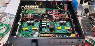
One thing I can report is that AC heaters and the +15V rail from voltage doubling all from a single heater winding works well (The AC heaters sit at a DC level of half that +15V supply because of the voltage doubler hung across it). Important to NOT add pseudo centre tap resistors. No HuMMM.
Those 2 fuse holders in the 1st picture are 1 each side of the transformers single 6.8 Amp heater winding (10 Amp Slow Blow fuses).
The RED LED front panel push switches are the input channel selection switches (in case I loose the remote). The Volume is remote controlled via motorised pot with slipping clutch so it can be set manually too. The Yellow LED is the remote control acknowledge LED. The selector board at the rear has provision for Op Amp buffer and Gain but I've left all that out.
Cheers,
Ian
That should improve the linearity of the diff amp / phase splitter.
Your estimate of approximately 35V bias on the KT77 meaning the diffamp must swing +/- 35V peak or 70V pk-pk is about right.
How much CURRENT the diffamp must swing to produce that 70V pk - pk depends upon the amount of shunt feedback set by R13.
With it at 18K the diffamp seems to be coping OK (amp sensitivity is fine) but as you increase that R13 you throw extra demands on the 12AX7.
With much more feedback
and /or
lower gm output tubes
and/or
higher voltage operation
then you will need to add an extra gain stage. I don't have a real feel for that yet.
One thing I can report is that AC heaters and the +15V rail from voltage doubling all from a single heater winding works well (The AC heaters sit at a DC level of half that +15V supply because of the voltage doubler hung across it). Important to NOT add pseudo centre tap resistors. No HuMMM.
Those 2 fuse holders in the 1st picture are 1 each side of the transformers single 6.8 Amp heater winding (10 Amp Slow Blow fuses).
The RED LED front panel push switches are the input channel selection switches (in case I loose the remote). The Volume is remote controlled via motorised pot with slipping clutch so it can be set manually too. The Yellow LED is the remote control acknowledge LED. The selector board at the rear has provision for Op Amp buffer and Gain but I've left all that out.
Cheers,
Ian
Last edited:
- Home
- Amplifiers
- Tubes / Valves
- EL34 Baby Huey Amplifier