Hello FLima,
Interesting reading!
Myself, I'd like to try an Rk of 250R but think I'd be taxing the PT too much. It's already quite toasty after an hour or two ��.
Also, my household voltage varies from 235-240 depending if my amp is on, LOL, and if my outlander phev is charging or not so I decided to leave a safety margin. Also, I ordered these OPTs on AliExpress:
£15.65 6%OFF | 10w Single-ended 6P6P EL34 FU50 FU7 tube amp output audio transformers 3.5k output of 0-4-8 Ohm 1pcs
10w Single ended 6P6P EL34 FU50 FU7 tube amp output audio transformers 3.5k output of 0 4 8 Ohm 1pcs|tube amp|audio ampel34 amp - AliExpress
and, again, safety margin. They seem just the fit for our amp and may interest some of you.
I'm happy with the sound but yearn for a little more bass.
It appears brighter since putting in the 270R KRs.
How did you plot the frequency response, if I may ask?
NB: If your capacitors are up to specs, you can simply swap out the original rectifier tube with a 5ar4/gz34 and your rails will gain an extra 20v.
Last edited:
Hi Tubby23,
Thanks for your comments.
I would be very interested in replacing the OPTs since I think they are a weak point in the amp, but I'd need to be sure they will perform better than the originals. Have you installed them yet? if yes, have you noticed improvement in power output and/or sound quality? Please share the results with us. It will be very interesting data for all of us.
Could the lack of bass be because of the speaker? Mine has good bass even with 250 ohms Rk (Actually I wish mine had a bit more high frequency). Does the bass improves with higher value Rk?
Replacing the rectifier tube interest me, but what do you mean by "capacitors are up to specs"? I assuming it is if they're spec'd for the new higher voltage they'll have to operate.
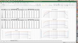
Regarding how I plotted the frequency response graph, I used our good old friend Excel. There is a function in Excel where you can plot graphics using log scale in the horizontal axis.
Here's the link to my Excel. Just fill out the yellow cells and Excel will do the rest. Lima's A9 Amp Frequency Response.xlsx - Google Drive
Cheers.
FLima

Thanks for your comments.
I would be very interested in replacing the OPTs since I think they are a weak point in the amp, but I'd need to be sure they will perform better than the originals. Have you installed them yet? if yes, have you noticed improvement in power output and/or sound quality? Please share the results with us. It will be very interesting data for all of us.
Could the lack of bass be because of the speaker? Mine has good bass even with 250 ohms Rk (Actually I wish mine had a bit more high frequency). Does the bass improves with higher value Rk?
Replacing the rectifier tube interest me, but what do you mean by "capacitors are up to specs"? I assuming it is if they're spec'd for the new higher voltage they'll have to operate.
Regarding how I plotted the frequency response graph, I used our good old friend Excel. There is a function in Excel where you can plot graphics using log scale in the horizontal axis.
Here's the link to my Excel. Just fill out the yellow cells and Excel will do the rest. Lima's A9 Amp Frequency Response.xlsx - Google Drive
Cheers.
FLima
Attachments
Last edited:
Fdlima, thanks for the Excel sheet - I'll try that.
Regarding caps being to spec - yes, I meant rated voltages.
My c301 and c302 are rated at 450v with c303 being 400v.
With the original tubes and rectifier I was getting B+ of 377v and B2 of 328v. If you stick in the 5ARG only these would rise to about 397v and 348v respectively with another 15v at pin 8 of the rectifier. So best to upgrade your caps.
I only just ordered the transformers - i expect them to take a month at least to arrive, but I'll keep you posted.
Fdlima,
Regarding the lack of bass, it's because our OEM transformers are small. If you look around at single ended, single tubed, tube amps, you'll see the better ones have large OPTs even though they can only potentially output up to 10w as ours.
Single ended OPTs must have an air gap in the laminations to prevent the core from saturating from the bias and one way signal current - it's pulsed DC, not AC.
The problem with having the air gap is the transformer contains less iron for a given size.
And ours are already small to begin with so they saturate from low frequencies.
All bigger OPTs will achieve is lower bass not more power.
VU Meters
Hi Filma,
I am seriously considering your suggestion of adding VU meters to my unit.
I plan on purchasing 2 x 34mm dia VU meters and a buffer driver board. I am assuming that the L/R audio in contacts on the buffer board are simply connected to L/R audio out contacts on my preamp tone control board and the outs go to the VU's. Hope that makes sense.
Cheers,
Bob
It looks pretty cool. Congratulations.
Since you have metal work skills, and have space in from panel, why not add VUs to make it look very vintage?
Flima
Hi Filma,
I am seriously considering your suggestion of adding VU meters to my unit.
I plan on purchasing 2 x 34mm dia VU meters and a buffer driver board. I am assuming that the L/R audio in contacts on the buffer board are simply connected to L/R audio out contacts on my preamp tone control board and the outs go to the VU's. Hope that makes sense.
Cheers,
Bob
Hi Bob.
Yes, it is very simple. Just connect the L/R inputs of the VU driver board at the speaker terminals in the amp. I connected them to the 4ohms terminals. I used the HI impedance inputs (2.4K ohms) of the VU driver not add any additional load to the amp output.
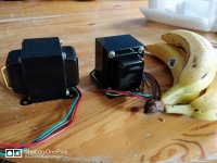
Please note that you will need a separate 12V transformer to power the VU meter but my board already had the rectifier and voltage regulator built-in so I just got a simple transformer and connected its AC directly to the VU driver board.
Power Transformer 12.6V-300mA: Amazon.com: Industrial & Scientific
Here are some pictures of how I mounted in the chassis. Let me know if you have any questions.
Cheers,
Flima


.jpg")
Yes, it is very simple. Just connect the L/R inputs of the VU driver board at the speaker terminals in the amp. I connected them to the 4ohms terminals. I used the HI impedance inputs (2.4K ohms) of the VU driver not add any additional load to the amp output.
Please note that you will need a separate 12V transformer to power the VU meter but my board already had the rectifier and voltage regulator built-in so I just got a simple transformer and connected its AC directly to the VU driver board.
Power Transformer 12.6V-300mA: Amazon.com: Industrial & Scientific
Here are some pictures of how I mounted in the chassis. Let me know if you have any questions.
Cheers,
Flima
VU Meters
Hi Flima,
Thanks for the swift reply and images.
I have ordered components from a locally based Aussie manufacturer/supplier
and await delivery.
Cheers,
Bob
Hi Flima,
Thanks for the swift reply and images.
I have ordered components from a locally based Aussie manufacturer/supplier
and await delivery.
Cheers,
Bob
Upgrade OPTs
@flima
I've completed the upgrade and the bass has much more presence and impact! With a dummy load, my oscilloscope shows clean sine waves down to 30mhz! Visible distortion only begins at 20mhz however the the other end distortion starts at about 15khz.. I can only hear up to 13khz anyways..
These OPTs, having about 100 ohms more of DC resistance than the stock ones had me concerned about lowering the bias but measurements showed all my voltages are about the same with Plate current at 63.5mA, same as before with 270R cathode resistors.
Also, these OPTs can be screwed into the A9 chassis without having to drill additional holes using the same M4 screws that held the OEM OPTs.
Their footprint covers most of the holes already there but I just positioned them frontmost, covering those and leaving a few uncovered at the rear.
I did experience an oscillation noise which took some experimentation and research to work it out.
It was down to the ultralinear wires from both OPTs being bunched together and they were interfering with eachother.
The effect was a 500hz noise in the left channel.
I cleaned up my lead dressing and it's super quiet when it's supposed to be!
I also took the opportunity to replace the crappy RCA jack's with gold plated high quality ones.
I'm very happy and I've reached a point in that I'm actually "finished" with my A9 - it's complete.
Last edited:
Last edited:
Hi - Quick Question - I want to put the triode/pentode switch in but just wanted to ask if I needed a 500V switch, or would a 250V DPDT do? Thanks
Hello Tubby23, i sincerely admire all the work you have done with this amp. well done
Thank you Sir!
Hi - Quick Question - I want to put the triode/pentode switch in but just wanted to ask if I needed a 500V switch, or would a 250V DPDT do? Thanks
I used this switch.
But you only throw it when the amp is off to maximize lifespan.
Heschen metal toggle switch 3PDT maintained ON/ON 2 position 15A 250VAC 10A 380VAC CE: Amazon.co.uk: Car & Motorbike
Changing the position of a screen switch when any amplifier is powered will cause the tweeter to receive a very powerful, if short time transient.
And, the output transformer may not like that very much either.
And your ear will receive a very loud high frequency transient.
That is true for a 125V switch, and for a 1500V switch.
Do not do that.
And, the output transformer may not like that very much either.
And your ear will receive a very loud high frequency transient.
That is true for a 125V switch, and for a 1500V switch.
Do not do that.
Changing the position of a screen switch when any amplifier is powered will cause the tweeter to receive a very powerful, if short time transient.
And, the output transformer may not like that very much either.
And your ear will receive a very loud high frequency transient.
That is true for a 125V switch, and for a 1500V switch.
Do not do that.
And doesn't do the switch itself any favours either.
In fact, it's not good enough to throw it just after switching off the amp. You must wait about 10 seconds for the caps to discharge s well.
On mine, I installed an led live indicator inside the chassis and I always wait for it to go out before throwing the switch.
Last edited:
@Tubby23,
Thanks for sharing the results of your testing. Very useful information.
Did you see any performance improvement, i.e. more power out of OPT with same input signal? I'm curious to see if this new OPT has less loss than the stock OPT.
Cheers,
Flima
Thanks for sharing the results of your testing. Very useful information.
Did you see any performance improvement, i.e. more power out of OPT with same input signal? I'm curious to see if this new OPT has less loss than the stock OPT.
Cheers,
Flima
Last edited:
And doesn't do the switch itself any favours either.
In fact, it's not good enough to throw it just after switching off the amp. You must wait about 10 seconds for the caps to discharge s well.
On mine, I installed an led live indicator inside the chassis and I always wait for it to go out before throwing the switch.
Just curious, but do you ever use the switch, or just put it into triode mode and leave it there? I may just save myself some drilling ;-)
I had switches fitted for UL / Triode but I couldn't decide if there was any "improvement" in the sound in either mode. I ended up leaving it UL most of the time.
I've now reconnected the outputs in UL mode and I use the switches to activate plate to plate feedback which does change the sound a great deal. It's just a connection between the plates with a resistor. I went for 330k but anything over 200k is OK depending on how much voltage you want to drop.
I'd definitely recommend it....
Last edited:
- Home
- Amplifiers
- Tubes / Valves
- Boyuu EL34 A9 Tube Amp