So the constant impedance isn't that important after all, is it.True that!
With FIR, even a non-minimum phase anomaly is correctable.
//
I know of very good waveguides that don't have the impedance constant anywhere... All this is implicitly handled in the crossover design.
Last edited:
Well, not for modern thinking people 🙂
Somehow though, maybe?, having a naturally correct system might have a bit of advantage - thats the common understanding - right?
One could leave on stage out of the system.
//
Somehow though, maybe?, having a naturally correct system might have a bit of advantage - thats the common understanding - right?
One could leave on stage out of the system.
//
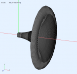
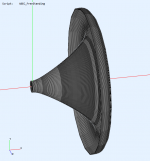
I'd like to simulate the behaviour when made from segments like on the picture but unfortunately that's not how the mesh is generated anymore... Otherwise it would be easy to make such a horn from e.g. balsa (wood) stripes.
(To explain - this is only a simplified visualization in the CircSym mode; it is actually solved for a perfectly axisymmetric shape, not segmented like this.)
Darn! When I saw those pictures last night I had similar thoughts re. making a "petal horn" with the technique you describe.
Bill
Axial motion? 🙂
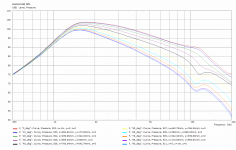
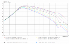
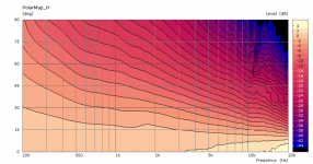
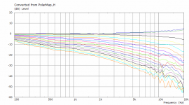
Yes, the driver is set to axial motion, with the elements of the surround set to varying drive values per my posted formulas earlier in this thread. For the dayton tweeter, the inner half of the surround is 0.53 and the outer is 0.18 in order to match the Sd in the data sheet.
That said, I've noticed that the driving values (and the surround geometry itself) play a large roll in top octave performance. My next experiments will be looking into ways to improve this area.
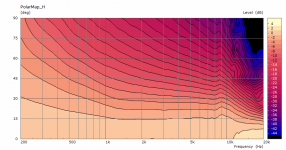
Two pictures attached - one with the surround driving values .53 and .18 ("normal surround" values) and the other with all values set to 1 ("driving surround"), for illustration.
Attachments
I could make an output of the templates for the unfolded petals if there was an interest. We have the profile templates already.Darn! When I saw those pictures last night I had similar thoughts re. making a "petal horn" with the technique you describe.
Bill
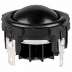
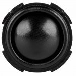
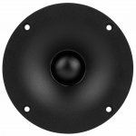
Dayton ND25FN(aked) versus ND25FW(aveguide).
Attachments
-
 dayton-audio-nd25fn-4-1-silk-dome-neodymium-tweete.jpg81 KB · Views: 325
 -
 dayton-audio-nd25fn-4-1-silk-dome-neodymium-tweete-2.jpg103.7 KB · Views: 320
 -
 dayton-audio-nd25fw-4-1-soft-dome-neodymium-tweete-2.jpg75.8 KB · Views: 325
 -
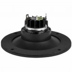 dayton-audio-nd25fw-4-1-soft-dome-neodymium-tweete-1.jpg52.6 KB · Views: 135
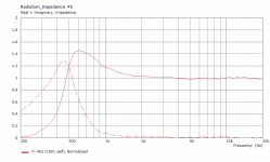
So the constant impedance isn't that important after all, is it.
The radiation impedance level is not so important because the efficiency of the system is so low. A change in rad imp of 20% will only equate to something like 1 dB of output.
Now when this impedance drops to near zero, then we call that "cutoff" and it makes a big difference.
What has major effects is an electrical impedance that swings due to internal resonances. This is a big problem with a passive crossover.
I have been watching your thread with great interest (and admiration!), dreaming of constructing waveguides based on your techniques.
This possibility of "petal horns" gave nice food for thought, though I wondered if the "lack of smoothness" would have any effects. I was going to start searching for "petal" horn construction techniques this morning; I think I have seen some guides before.
I have also been happy that it appears your latest program allows for much faster simulation. I am close to computer-illiterate, and don't have a PC (Mac only), so I am pleased to see new sims, hoping secretly that you will do some for horns that reach lower in frequency (B&C DCM 414 or DCM 420 for 300-6K and even for Celestion's axi for 300 Hz all the way up). Pattern control down to 300 Hz is intriguing, and if I build something I wouldn't mind going big. 🙂
Bill
If you don't mind beaming and are willing to host a giant horn, it's perfectly possible.
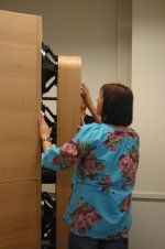
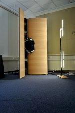
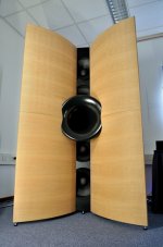
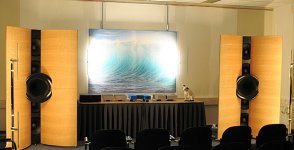
This fully horn-loaded prototype loudspeakersystem - developed in just 2 months, was voted 'best-of-show' by most visitors almost 10 years ago.
It's capable of 15Hz>20kHz, but was tuned slightly higher (20Hz). Crossover to the mid/high horn was 270Hz.
This fully horn-loaded prototype loudspeakersystem - developed in just 2 months, was voted 'best-of-show' by most visitors almost 10 years ago.
It's capable of 15Hz>20kHz, but was tuned slightly higher (20Hz). Crossover to the mid/high horn was 270Hz.
Attachments
Last edited:
I still have issues with splitting the high frequencies between more horns, I don't think it is a good idea - I consider a proper integration hardly possible. That's why I don't even think about designing such horns. All such systems I heard sounded flawed to me.
If you don't mind beaming and are willing to host a giant horn, it's perfectly possible.
So would an OS shape with your mouth termination technique to eliminate the on-axis null not be practical? Maybe simply because of the difficulty with construction.
I watched "camplo's" thread with the AXI-, but he was pursuing a beaming/diffraction approach.
I would likely have to scale back my ambition....
But at least I am forcing myself to try and learn. I just printed out the pdf guide! Maybe my intelligent son can help on his PC. My clerk brought it to me with a look of bewilderment 🙂
Bill
I still have issues with splitting the high frequencies between more horns, I don't think it is a good idea - I consider a proper integration hardly possible. That's why I don't even think about designing such horns. All such systems I heard sounded flawed to me.
Yes, that is obviously the drawback, though I have read that at high frequencies it is perhaps less critical? Conversely, I am concerned about C-C distance when crossing over at the usual 800- 1.2k. Crossing at the approximate Schroeder frequency of the room (250-300 Hz) seems less problematic(?).
In my DIY efforts (no speakers yet) I try to minimize the potential physics pitfalls/difficult areas with "brute force," and of course a bit more money (the latter approach is certainly less elegant than many of you are able to achieve through better engineering skills).
The idea of one driver/no crossover in the 300-6 kHz range is appealing, though I would probably go with the Celestion to eliminate the upper crossover.
Bill
In the recent posts I showed some big OS waveguides for 1.4" or even 2" drivers... 🙂
Yes, those are the ones I was excited to see! One close to a meter wide, I think!
I think that pattern control was down to maybe 800 Hz? I need to look again.
Perhaps the large Faital that seems to be getting popular is a more prudent approach.
Bill
BTW, if you live in Prague per your signature, I am jealous. My wife and I fell in love with the city a few years ago celebrating our 25th anniversary. Simply fantastic. Our country is so young compared to the old European cities. We don't have anything close. And it was the first time I enjoyed a Pilsner. Even yours that they import here, by the time they get to us aren't very good 🙂
If you don't mind beaming and are willing to host a giant horn, it's perfectly possible.
This fully horn-loaded prototype loudspeakersystem - developed in just 2 months, was voted 'best-of-show' by most visitors almost 10 years ago.
It's capable of 15Hz>20kHz, but was tuned slightly higher (20Hz). Crossover to the mid/high horn was 270Hz.
I remember seeing that one at the time!
Bill
Take my word for it, that system didn't suffer from any 'noticeable' crossover artefacts.
There are only 2 horns involved, however, for the mid/high horn a modified BMS Coaxial is used.
The OB horn is quite special, it's designed to cancel room modes.
The guys could almost literally shake the hotel where the show took place, though without annoying adjacent rooms - contrary to the top-of-the-line PMC large format studio monitors, that were also demoed.
The designer has expressed interest in OS horns, after a client of his built Summas and praised the wide coverage of the system.
Well this is about the kind of beaming you would have to accept if you used a 2" driver like the big Celestion, at least without employing any diffraction techniques. This is about the best I can get out of it - maybe someone else could do better. Honestly, I don't know if this is exactly what to go for. Maybe.
(⌀800 x 376 mm).
(⌀800 x 376 mm).
Attachments

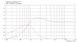
The radiation impedance level is not so important because the efficiency of the system is so low. A change in rad imp of 20% will only equate to something like 1 dB of output.
Now when this impedance drops to near zero, then we call that "cutoff" and it makes a big difference.
What has major effects is an electrical impedance that swings due to internal resonances. This is a big problem with a passive crossover.
The real part is pure efficiency - right? But how about the reactive part - isn't that a bit more problematic as it changes the phase?
//
- Home
- Loudspeakers
- Multi-Way
- Acoustic Horn Design – The Easy Way (Ath4)