On 18V:
- D voltages: 16.8V on both
- S voltages: 0.2V on both
On 9V:
- D votages: 8.1V on both
- S voltages: 0.14V on both
I simply do not believe those values.
Which FETs did you say you were using?
Rick´s simulation on post #50 agrees with my calculations (I do not simulate): about 750mV at the bias divider, and about 2.8V at FET Source.
That is a simulation, whichb relies on a theoretical model, based on experience I would expect between 2.5V (very good quality selected FET) to around 3V (average one) to about 3.5V (beyond which it "should" be sold as a cheaper one) but in any case you are showing IMPOSSIBLE 0.15 to 0.25 V. NO WAY.
Please link to your FET suppliers to see what they claim.
Results are SO bad/incredible they might even be ... plain Bipolars .... go figure.
How much did you pay for them?
2N5457, IF available, cost around $5/$7 *each*.
As a side note, buy a few plentiful and cheap J111/112/113 from Mouser, Farnell, Digikey, etc. , NOT from EBay or AliBaba.
Low spec as they are, at least they are real 😎
I bought 1000 J112 from Mouser at 10 cents each, go figure.
Can´t edit above answer so I add it here.
I searched for them,found them at Amazon, 20 for 11 bucks.
Too good to be true.
Buyer comments:
Mouser shows ON original ones *unavailable* for years now, there is a "second source" supplier, Central Semiconductor,which jumps in to cover any missing/obsolete semiconductor.
In my view, I find it hard to believe they can manufacture "everything" in small quantities and at low prices, no proof but I suspect (take this with a grainh ofn salt) that maybe they buy remaining stock from closing factories (maybe even unmounted dies) , and when they see a market hole they package something they have, more or less close, and label it accordingly.
Find strange that huge factories can not make many models any more, even less through hole, while CSC can.
Most European and American factories closed and oitsourced or moved to Asia and they hafe a factory , not only in USA (say Arizona or something) , not even in Silicon Valley, but in Long Island? ... a couple miles from Manhattan? Weird.
I´d expect a warehouse there, not much more.
Oh, the Amazon ones come from SISTOCK ... "FuTian , ShenZhen, China"
I searched for them,found them at Amazon, 20 for 11 bucks.
Too good to be true.
Buyer comments:
Verified Purchase
The data sheet states a Vgs of -.5V - -6V, I was hoping out of 20 to get at least a few in the 2+ range. All 20 tested at around -.3V making them pretty useless for a guitar preamp as they clip (overdrive) from just the guitar signal.
If lesser jfets are acceptable for your application, this is a great price. But if you need higher quality, spend the money and get them from a reputable electronics store.
Verified Purchase
Just like others have stated these are likely real but have low values. They are very low gain in a Morning glory overdrive I built (low but useable for sure, just not ideal). I I ended up liking a J113 better for this application.
Incorrect Vgs(off)
Was worried these wouldn’t be legitimate since it’s hard to find 2N5457’s anymore. Current values were to their specification, but not Vgs(off) values. They can still be used, but not for all applications. I would get the MMBF5457 (SMD version) instead.
Mouser shows ON original ones *unavailable* for years now, there is a "second source" supplier, Central Semiconductor,which jumps in to cover any missing/obsolete semiconductor.
In my view, I find it hard to believe they can manufacture "everything" in small quantities and at low prices, no proof but I suspect (take this with a grainh ofn salt) that maybe they buy remaining stock from closing factories (maybe even unmounted dies) , and when they see a market hole they package something they have, more or less close, and label it accordingly.
Find strange that huge factories can not make many models any more, even less through hole, while CSC can.
Most European and American factories closed and oitsourced or moved to Asia and they hafe a factory , not only in USA (say Arizona or something) , not even in Silicon Valley, but in Long Island? ... a couple miles from Manhattan? Weird.
I´d expect a warehouse there, not much more.
Oh, the Amazon ones come from SISTOCK ... "FuTian , ShenZhen, China"
I simply do not believe those values.
Which FETs did you say you were using?...
How much did you pay for them?
2N5457, IF available, cost around $5/$7 *each*...
Please link to your FET suppliers to see what they claim...
Ok, this is interesting. The label on them is 2N5457, with the "F" for Fairchild branding. These are ebay ones, check the link below, the exact I got them from. I won't be surprised if they are not up to the "genuine" 2n5457's.
I got 10 for about $4-5... the cost you say one should be.....
10PCS 2N5457 2N5457G TO-92 N-Channel TransistorBDAU
Rick´s simulation on post #50 agrees with my calculations (I do not simulate): about 750mV at the bias divider, and about 2.8V at FET Source.
That is a simulation, whichb relies on a theoretical model, based on experience I would expect between 2.5V (very good quality selected FET) to around 3V (average one) to about 3.5V (beyond which it "should" be sold as a cheaper one) but in any case you are showing IMPOSSIBLE 0.15 to 0.25 V. NO WAY.
Results are SO bad/incredible they might even be ... plain Bipolars .... go figure.
I trust you both, the voltages, especially being even below 1V are unsual to me too but I can't say if they are bad or not. So if you think they are off I trust that.
As a side note, buy a few plentiful and cheap J111/112/113 from Mouser, Farnell, Digikey, etc. , NOT from EBay or AliBaba.
Low spec as they are, at least they are real 😎
I bought 1000 J112 from Mouser at 10 cents each, go figure.
Are these a direct replacement and is it better than to find the "genuine" 2N5457? Smallbear has them but has limit of 5pcs, and i need 5 pairs... The guy says they are 100% genuine and sells them for $0.75 each. A lot of people have claimed they "seem" to be genuine but are not that expensive, rather more or less as much as i got them. So yeah, hell if I know what's real what not now
Can´t edit above answer so I add it here.
I searched for them,found them at Amazon, 20 for 11 bucks.
Too good to be true.
Buyer comments:
Verified Purchase
The data sheet states a Vgs of -.5V - -6V, I was hoping out of 20 to get at least a few in the 2+ range. All 20 tested at around -.3V making them pretty useless for a guitar preamp as they clip (overdrive) from just the guitar signal.
If lesser jfets are acceptable for your application, this is a great price. But if you need higher quality, spend the money and get them from a reputable electronics store.
Verified Purchase
Just like others have stated these are likely real but have low values. They are very low gain in a Morning glory overdrive I built (low but useable for sure, just not ideal). I I ended up liking a J113 better for this application.
Incorrect Vgs(off)
Was worried these wouldn’t be legitimate since it’s hard to find 2N5457’s anymore. Current values were to their specification, but not Vgs(off) values. They can still be used, but not for all applications. I would get the MMBF5457 (SMD version) instead.
Mouser shows ON original ones *unavailable* for years now, there is a "second source" supplier, Central Semiconductor,which jumps in to cover any missing/obsolete semiconductor.
In my view, I find it hard to believe they can manufacture "everything" in small quantities and at low prices, no proof but I suspect (take this with a grainh ofn salt) that maybe they buy remaining stock from closing factories (maybe even unmounted dies) , and when they see a market hole they package something they have, more or less close, and label it accordingly.
Find strange that huge factories can not make many models any more, even less through hole, while CSC can.
Most European and American factories closed and oitsourced or moved to Asia and they hafe a factory , not only in USA (say Arizona or something) , not even in Silicon Valley, but in Long Island? ... a couple miles from Manhattan? Weird.
I´d expect a warehouse there, not much more.
Oh, the Amazon ones come from SISTOCK ... "FuTian , ShenZhen, China"
Ok now this seems to make some sense at least for the transistors. Thanks for the research.
But then, why do they work so nice with one source 47uF cap fitted in the 2nd stage? Is it cause of the huge boost added by the cap? Rick is saying this (the high value source R's with the cap in) impacts dynamic range, i'm not sure i can hear a difference or i'm not listening to what i need to i guess... i have no idea. The bass can produce pretty high frequncies i think that would probably be compromised by the dynamic range issue, i don't know, the pickup that i use is pretty much a "high definition" modern type, brand new strings, Gallien Krueger amp with Ampeg PF-210HE cabinet with horn which goes above 10kHz. So yeah, i'm 110% baffled
I can't use SMD at this point as the PCB is already made, the only substitute that could work is something that's a direct replacement
Last edited:
One thing is certain, these are NOT 2N5457 no matter what´s printed on the case.
Just found these other:
10PCS 2N5457 2N5457G TO-92 N-Channel TransistorBDAU | eBay

10 for U$1.60 ... IMPOSSIBLE
Sadly J111/12/13 are cheap *switching* Fets, with too high Vp around 4V.
They *can* be used as Preamp stages but need some 20/25V +V supply to get reasonable gain, you can make a Randall preamp with them (selecting a little), but 9V supply is too low, worst case you could use 18V, remember you are "wasting" around 4V to begin with.
I am more and more convinced you got cheap bipolars, what else?
An N Ch FET will **always** as in ALWAYS have its gate more NEGATIVE than Source, so Source more positive than what it gets at its gate.
So with Gate biased to +0.75V (I am rounding numbers off) Source should be more positive, period.
Simulation expects +2.75V at Source.
BUT you have "Gate" (+0.75) more positive than Source (+0.14) , difference +0.6V , what I would expect at an NPN BIPOLAR transistor, barely turned on, never on a FET.
I can hear you think: "nice, but is any way to solve this mess?"
Maybe, at least you can try.
Plan A: get the MOUSER 2N5457 "made" by Central Semiconductor
Doubt they are full spec real ones, but at least they "should" be real Fets.
I can reasonably trust them working on your current PCB; maybe later they can be tweaked but they should be usable as is.
Plan B: you will hate me for this, but .... for now forget this FET based preamp (now you know why Fets fell out of favor, too temperamental) and build an Op Amp based preamp.
A TL062 is as plain vanilla as can be, needs low current and is "lowish spec" in an Audiophile Preamp, yet WAY more than enough for a Bass Guitar.
About 50 cents, will guaranteed work in he proper circuit without fuss and nobody will fake it, not expensive/rare/desirable enough.
Boring? ... maybe, but remember a famous Chinese curse is: "may you live in interesting times"
Sometimes boring dependable is GOOD!
Just found these other:
10PCS 2N5457 2N5457G TO-92 N-Channel TransistorBDAU | eBay
10 for U$1.60 ... IMPOSSIBLE
Sadly J111/12/13 are cheap *switching* Fets, with too high Vp around 4V.
They *can* be used as Preamp stages but need some 20/25V +V supply to get reasonable gain, you can make a Randall preamp with them (selecting a little), but 9V supply is too low, worst case you could use 18V, remember you are "wasting" around 4V to begin with.
I am more and more convinced you got cheap bipolars, what else?
An N Ch FET will **always** as in ALWAYS have its gate more NEGATIVE than Source, so Source more positive than what it gets at its gate.
So with Gate biased to +0.75V (I am rounding numbers off) Source should be more positive, period.
Simulation expects +2.75V at Source.
BUT you have "Gate" (+0.75) more positive than Source (+0.14) , difference +0.6V , what I would expect at an NPN BIPOLAR transistor, barely turned on, never on a FET.
I can hear you think: "nice, but is any way to solve this mess?"
Maybe, at least you can try.
Plan A: get the MOUSER 2N5457 "made" by Central Semiconductor
Doubt they are full spec real ones, but at least they "should" be real Fets.
I can reasonably trust them working on your current PCB; maybe later they can be tweaked but they should be usable as is.
Plan B: you will hate me for this, but .... for now forget this FET based preamp (now you know why Fets fell out of favor, too temperamental) and build an Op Amp based preamp.
A TL062 is as plain vanilla as can be, needs low current and is "lowish spec" in an Audiophile Preamp, yet WAY more than enough for a Bass Guitar.
About 50 cents, will guaranteed work in he proper circuit without fuss and nobody will fake it, not expensive/rare/desirable enough.
Boring? ... maybe, but remember a famous Chinese curse is: "may you live in interesting times"
Sometimes boring dependable is GOOD!
OK, what about the small bear electronics ones?One thing is certain, these are NOT 2N5457 no matter what´s printed on the case.
Then they are definitely not a good fit for a battery preampSadly J111/12/13 are cheap *switching* Fets, with too high Vp around 4V.
They *can* be used as Preamp stages but need some 20/25V +V supply to get reasonable gain, you can make a Randall preamp with them (selecting a little), but 9V supply is too low, worst case you could use 18V, remember you are "wasting" around 4V to begin with.
OK, so bipolars are a direct replacement for FET's then cause they work in the same circuit?I am more and more convinced you got cheap bipolars, what else?
Didn't know this, good info to know though, thanks!An N Ch FET will **always** as in ALWAYS have its gate more NEGATIVE than Source, so Source more positive than what it gets at its gate.
So with Gate biased to +0.75V (I am rounding numbers off) Source should be more positive, period.
Simulation expects +2.75V at Source.
BUT you have "Gate" (+0.75) more positive than Source (+0.14) , difference +0.6V , what I would expect at an NPN BIPOLAR transistor, barely turned on, never on a FET.
Plan A: it'd definitely the best option if I can use them without modifying the PCB. Seems like Mouser just got stock of them, when I was getting the other components it wasn't available. What about small bear electronics? The guy could possibly test them.I can hear you think: "nice, but is any way to solve this mess?"
Maybe, at least you can try.
Plan A: get the MOUSER 2N5457 "made" by Central Semiconductor
Doubt they are full spec real ones, but at least they "should" be real Fets.
I can reasonably trust them working on your current PCB; maybe later they can be tweaked but they should be usable as is.
Plan B: you will hate me for this, but .... for now forget this FET based preamp (now you know why Fets fell out of favor, too temperamental) and build an Op Amp based preamp.
A TL062 is as plain vanilla as can be, needs low current and is "lowish spec" in an Audiophile Preamp, yet WAY more than enough for a Bass Guitar.
About 50 cents, will guaranteed work in he proper circuit without fuss and nobody will fake it, not expensive/rare/desirable enough.
How do you test that voltage btw on a FET?
Plan B: I already have an opamp based one that I made about month ago (from the other thread, I think you contributed there too), with Baxandall tone control and it work great. So I'd want one transistor based, specifically this one. I wouldn't have the time to go over other circuits and have them tested from scratch to see what I'd like. This is a great one.
True in some cases...Boring? ... maybe, but remember a famous Chinese curse is: "may you live in interesting times"
Sometimes boring dependable is GOOD!
SmallBear's parts are what he says. It either is genuine production, or for some odd parts Steve has done the work to find a part which "works-alike" (in some specified pedal).
If he limits to 5 and you want 10, write to him. What he really wants to avoid is speculators buying huge quantity "for investment". If you have your own project which needs a few more, he'll try to get you going.
Note that he also has "odd number" JFETs which he sorts for Idss and Vp, and sells to your request.
Ok, that seems good enough. I used to buy some bits from Steve a long time ago and everything seemed pretty much on point with what was selling.SmallBear's parts are what he says. It either is genuine production, or for some odd parts Steve has done the work to find a part which "works-alike" (in some specified pedal).
If he limits to 5 and you want 10, write to him. What he really wants to avoid is speculators buying huge quantity "for investment". If you have your own project which needs a few more, he'll try to get you going.
Note that he also has "odd number" JFETs which he sorts for Idss and Vp, and sells to your request.
So for this preamp I need to ask for Vp between 2 - 3V, and matched Idss per pair, or do I just need a specific Idss without matching?
What should I ask for?
Sorry I've been slow getting back to you. Thanks JMFahey for stepping in to help when I went dark.😱
One thing worth noting, though -- we have an assortment of measurements using different Source resistances 'cause we had trimpots fitted, bias and Source resistors.
I'm pretty sure these transistors will work just fine -- as soon as we find a reasonably linear operating point. Despite the best efforts of my dozen or so finest brain cells, I haven't yet come up with a 'just right' suggestion for the bias voltage.
We could, of course, perform a detailed assay (if that's the right word😉) of Drain voltage vs bias voltage vs battery current -- say, every 50mV or so of bias, up to maybe 1.3V. It surely would be interesting, if you have the time ..
On the other hand, we could just find the bias setting that gives a Drain voltage of approx mid-supply, say 9.5 to 11V. Just keep in mind, the Drain voltage will drop at about the same rate as the battery voltage, not proportionally -- 1V drop at the battery will be almost 1V drop at the Drain.
But I really think it'd be wise to put aside all listening tests until we've found that relative 'sweet spot' for the operating point.
Wish I could just give you a resistor value to set the bias (R2 in the schematic). And it is still possible that the Drain resistors will need to be increased to get the power consumption as low as you want it (with the original transistors). But these will work.
Cheers
edit: (took me since post 65 to gather these limited thoughts -- sorry😱) I would really hate to add still more transistor's variables to the project -- especially since OP already has 10 additional 2N5457's (alleged, possibly) on hand to try if necessary.
Last edited:
To cover a couple of bits from the last few posts ..
- no, bipolar transistors cannot substitute for JFET's in any circuit
- if you were still at the beginning of this project, it might be reasonable to start over with a different transistor; at this moment there's no reason to
- I think JMFahey may have crossed up measurements between different Source resistors -- pretty sure we haven't had any combinations that produced positive bias; but he's quite a bit sharper than me, so I could be wrong
By now you've probably realized that JFET's aren't at all *rollable* the way op-amps and many bipolar transistors are. A wide range can be made to work if you're willing to make adjustments to the circuit. But it isn't unusual for a JFET's two key characteristics, Idss and Vgs(off), to vary over a 4:1, 8:1 or even 12:1 range. No single circuit that can tolerate that, can maintain the same performance without change, unless the initial performance requirements had been gravely lowered.
Regards
With both 1M resistors connected to ground as suggested, should I be measuring 0V on Gate? That's what I'm getting
Haha your brain seems to work very fine Rick 😀
The essay idea would probably give us something, but having all this experimenting on a 23x23mm PCB is a little time consuming, it's just a little slow. But if I was still on a breadboard no problem then, much easier. I can definitely try something though...
Didn't we put a trimmer instead of R2 for a reason to find a value that would work...? I don't know what a decent curren draw in here is but probably below 1mA? One thing that I found is that most Aguilar preamps tend to have an estimate battery life od 324h, this isn't specifically mentioned for this circuit and it isn't given if this is at 9V or 18V, but i'm guessing it's for 18, if that serves as any indirect reference point..
I honestly don't know what to do next..... I really want to get this working, but if we're going to be stuck in this not sure if it's really worth it to consume everyone's time so much, there's one option only that works with one cap in the second stage that I can go with at the end... I don't know
It's all good Rick no need to apologize, just wanted to know how to plan the painting as it will take a while till everything is finished ready to be assembled backSorry I've been slow getting back to you. Thanks JMFahey for stepping in to help when I went dark.😱
One thing worth noting, though -- we have an assortment of measurements using different Source resistances 'cause we had trimpots fitted, bias and Source resistors.
I'm pretty sure these transistors will work just fine -- as soon as we find a reasonably linear operating point. Despite the best efforts of my dozen or so finest brain cells, I haven't yet come up with a 'just right' suggestion for the bias voltage.
We could, of course, perform a detailed assay (if that's the right word😉) of Drain voltage vs bias voltage vs battery current -- say, every 50mV or so of bias, up to maybe 1.3V. It surely would be interesting, if you have the time ..
Haha your brain seems to work very fine Rick 😀
The essay idea would probably give us something, but having all this experimenting on a 23x23mm PCB is a little time consuming, it's just a little slow. But if I was still on a breadboard no problem then, much easier. I can definitely try something though...
Ok, that's an interesting fact.On the other hand, we could just find the bias setting that gives a Drain voltage of approx mid-supply, say 9.5 to 11V. Just keep in mind, the Drain voltage will drop at about the same rate as the battery voltage, not proportionally -- 1V drop at the battery will be almost 1V drop at the Drain.
Ok then, this weekend I'll start preparing the bass for painting then and can do listening tests once all is doneBut I really think it'd be wise to put aside all listening tests until we've found that relative 'sweet spot' for the operating point.
Wish I could just give you a resistor value to set the bias (R2 in the schematic). And it is still possible that the Drain resistors will need to be increased to get the power consumption as low as you want it (with the original transistors). But these will work.
Didn't we put a trimmer instead of R2 for a reason to find a value that would work...? I don't know what a decent curren draw in here is but probably below 1mA? One thing that I found is that most Aguilar preamps tend to have an estimate battery life od 324h, this isn't specifically mentioned for this circuit and it isn't given if this is at 9V or 18V, but i'm guessing it's for 18, if that serves as any indirect reference point..
Ok so it seems the transistors are FETs.... whoa this thing with transistors is extremely fun.. said no one ever probably xD haha.- no, bipolar transistors cannot substitute for JFET's in any circuit
- if you were still at the beginning of this project, it might be reasonable to start over with a different transistor; at this moment there's no reason to
- I think JMFahey may have crossed up measurements between different Source resistors -- pretty sure we haven't had any combinations that produced positive bias; but he's quite a bit sharper than me, so I could be wrong
By now you've probably realized that JFET's aren't at all *rollable* the way op-amps and many bipolar transistors are. A wide range can be made to work if you're willing to make adjustments to the circuit. But it isn't unusual for a JFET's two key characteristics, Idss and Vgs(off), to vary over a 4:1, 8:1 or even 12:1 range. No single circuit that can tolerate that, can maintain the same performance without change, unless the initial performance requirements had been gravely lowered.
I honestly don't know what to do next..... I really want to get this working, but if we're going to be stuck in this not sure if it's really worth it to consume everyone's time so much, there's one option only that works with one cap in the second stage that I can go with at the end... I don't know
Last edited:
I am using *THIS* schematic because so far it´s the most reliable and clear and also has been simulated, showing the voltages I´d expect from a properly functioning circuit.
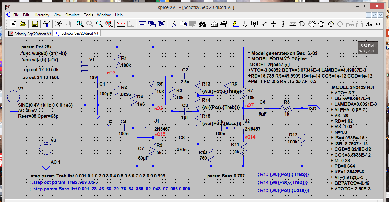
Only "problem" I might find with it, and it´s not actually a problem, but the difference between simulation and real world and its imperfections is that they use a Fet model (obviously 🙂 ) and then I will have random real parts on my bench.
Again, I have built hundreds of Fet preamps and simulated voltages look very reachable, it may take some Fet testing and selecting so "the head matches the hat" 🙂
Worst case, we can slightly mod the circuit values. (Vary source resistors and/or bias voltage divider)
I already uploaded this Mosfet matcher little circuit which I use for my own power MosFets (I commercially make Guitar/Bass/PA equipment) ; with a small variation it can be used for your purpose:
Screening parts for audio

For your Fets:
* replace +15V by 9V
* use Ground instead of -15V
* replace "my" R1 by "your" R9 value , so we test at the exact voltages and values needed in YOUR preamp, so use 4k7 Source to Ground.
* measure as suggested: Black probe to Ground, Red probe to Source, scale 20V .
You are measuring not really Vp but much better (because it´s your actual need) "Vgs needed to pass about 0.4mA" , because you need to drop some 4V across your load resistors, 10K R5 and R7
Never bought from Small Bear but he is much respected , of course anybody, including himself can be cheated by a supplier so I´d order from him but of course test before final assembly, if anything to tweak preamp for perfection.
Remember and repeat with me: "FETS are inconstant and can´t be trusted". 🙂
Roland, Yamaha and many others used a lot of them in the 70´s and 80´s buty being heavyweight manufacturers semiconductor factories bowed to them and supplied factory matched lots, identified by colour dots, so schematics ask for "2SKxxx(Y), (R), (G) , etc, meaning Yelloow, Red, Green, etc.
We do NOT have such a luxury.
Of course, fakers will paint them any colour that makes you happy 😡😡😡
MAYBE you can ask Small Bear to send you a pre matched lot for an extra fee so you don´t have to buy extras yourself.
Not sure he has time/manpower for that so if he can´t, he can´t.
And agree that he may be trying to keep hoarders away, just remember what happened with humble available anywhere toilet paper. 😱
Only "problem" I might find with it, and it´s not actually a problem, but the difference between simulation and real world and its imperfections is that they use a Fet model (obviously 🙂 ) and then I will have random real parts on my bench.
Again, I have built hundreds of Fet preamps and simulated voltages look very reachable, it may take some Fet testing and selecting so "the head matches the hat" 🙂
Worst case, we can slightly mod the circuit values. (Vary source resistors and/or bias voltage divider)
I already uploaded this Mosfet matcher little circuit which I use for my own power MosFets (I commercially make Guitar/Bass/PA equipment) ; with a small variation it can be used for your purpose:
Screening parts for audio
For your Fets:
* replace +15V by 9V
* use Ground instead of -15V
* replace "my" R1 by "your" R9 value , so we test at the exact voltages and values needed in YOUR preamp, so use 4k7 Source to Ground.
* measure as suggested: Black probe to Ground, Red probe to Source, scale 20V .
You are measuring not really Vp but much better (because it´s your actual need) "Vgs needed to pass about 0.4mA" , because you need to drop some 4V across your load resistors, 10K R5 and R7
Never bought from Small Bear but he is much respected , of course anybody, including himself can be cheated by a supplier so I´d order from him but of course test before final assembly, if anything to tweak preamp for perfection.
Remember and repeat with me: "FETS are inconstant and can´t be trusted". 🙂
Roland, Yamaha and many others used a lot of them in the 70´s and 80´s buty being heavyweight manufacturers semiconductor factories bowed to them and supplied factory matched lots, identified by colour dots, so schematics ask for "2SKxxx(Y), (R), (G) , etc, meaning Yelloow, Red, Green, etc.
We do NOT have such a luxury.
Of course, fakers will paint them any colour that makes you happy 😡😡😡
MAYBE you can ask Small Bear to send you a pre matched lot for an extra fee so you don´t have to buy extras yourself.
Not sure he has time/manpower for that so if he can´t, he can´t.
And agree that he may be trying to keep hoarders away, just remember what happened with humble available anywhere toilet paper. 😱
Last edited:
I am using *THIS* schematic because so far it´s the most reliable and clear and also has been simulated, showing the voltages I´d expect from a properly functioning circuit.
Only "problem" I might find with it, and it´s not actually a problem, but the difference between simulation and real world and its imperfections is that they use a Fet model (obviously 🙂 ) and then I will have random real parts on my bench.
Ok, see the attached circuit verison below, it's the only one that has worked for me with about 0.6-0.7mA current draw and that was really solid sounding. I'm not sure i can find any faults to it (i'm talking audible only and current draw). The onyl difference seems to be the location of the Source cap, in the simulation is in the first stage (where in my actual circuit distorts a lot), but if put in the second stage it works nice and current seems to be on point (as on the attache image below).
Whatever that can be moded I'm happy to do it while keeping the main traces as in the circuit below cause of the PCBAgain, I have built hundreds of Fet preamps and simulated voltages look very reachable, it may take some Fet testing and selecting so "the head matches the hat" 🙂
Worst case, we can slightly mod the circuit values. (Vary source resistors and/or bias voltage divider)
I checked it out, thanks for that Fahey, it would be of great help, you seem to be pretty ready for this kind of stuff 🙂I already uploaded this Mosfet matcher little circuit which I use for my own power MosFets (I commercially make Guitar/Bass/PA equipment) ; with a small variation it can be used for your purpose:
Screening parts for audio
Sorry, this got me a bit confused with R1 and R9, considering the attached circuit, you mean to R1 to be 10k or..?For your Fets:
* replace +15V by 9V
* use Ground instead of -15V
* replace "my" R1 by "your" R9 value , so we test at the exact voltages and values needed in YOUR preamp, so use 4k7 Source to Ground.
* measure as suggested: Black probe to Ground, Red probe to Source, scale 20V .
You are measuring not really Vp but much better (because it´s your actual need) "Vgs needed to pass about 0.4mA" , because you need to drop some 4V across your load resistors, 10K R5 and R7
"Minus" is GND now, no negative V, "-" is only cause of the battery Minus but it's GND actually in the circuit.
The guy seems to be reasonable and someone you can work with so i think if i'd need to buy some he could help out for extra "matching" fee and provide 5 pairs instead of 5pcs..Never bought from Small Bear but he is much respected , of course anybody, including himself can be cheated by a supplier so I´d order from him but of course test before final assembly, if anything to tweak preamp for perfection. MAYBE you can ask Small Bear to send you a pre matched lot for an extra fee so you don´t have to buy extras yourself.
Not sure he has time/manpower for that so if he can´t, he can´t.
Lmao, man this made me laugh, very true though xDRemember and repeat with me: "FETS are inconstant and can´t be trusted". 🙂
I know, this could be/is a factRoland, Yamaha and many others used a lot of them in the 70´s and 80´s buty being heavyweight manufacturers semiconductor factories bowed to them and supplied factory matched lots, identified by colour dots, so schematics ask for "2SKxxx(Y), (R), (G) , etc, meaning Yelloow, Red, Green, etc.
We do NOT have such a luxury.
Of course, fakers will paint them any colour that makes you happy 😡😡😡
Attachments
You guys are faster thinkers AND writers than I am! But before I finish reviewing the last few posts, thought it best to mention this ..
I hope we're still on the 1k8 Source resistors, and that neither is bypassed.
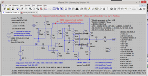
My bad on not properly labeling that LT Spice screen-shot with the orange-red node references. I only posted that one to show the operating point shortcomings of the original design. And that was despite simulating with a transistor model that is very different than the devices the OP originally fitted. Otherwise it differs markedly from the *most recent* version of the design. Sorry.🙁
Thankfully there's plenty of surplus gain, so we can trade some for a little better dynamic range, improved linearity, and reduced 'electrolytic capacitor sound'.
And remember, your meter can only measure Gate voltage at the other end of the 1 meg resistor -- the meter itself poses a significant load otherwise.
Best Regards
I hope we're still on the 1k8 Source resistors, and that neither is bypassed.
My bad on not properly labeling that LT Spice screen-shot with the orange-red node references. I only posted that one to show the operating point shortcomings of the original design. And that was despite simulating with a transistor model that is very different than the devices the OP originally fitted. Otherwise it differs markedly from the *most recent* version of the design. Sorry.🙁
Thankfully there's plenty of surplus gain, so we can trade some for a little better dynamic range, improved linearity, and reduced 'electrolytic capacitor sound'.
And remember, your meter can only measure Gate voltage at the other end of the 1 meg resistor -- the meter itself poses a significant load otherwise.
Best Regards
- no, bipolar transistors cannot substitute for JFET's in any circuit ...
It is trivial to devise a circuit where they CAN.
This one is a marginal "NO!" because of the huge (by BJT expectations) bias resistor.
IF the JFET is (Healthy! and) connected correctly it is not that hard to find a happy bias condition. This circuit makes it easier.
Simplify.
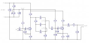
Here's what I thought we were currently working on ..
The one discrepancy is the bias divider. I wanted to try the 0V for a couple reasons -- 1) To confirm that the originally fitted transistors could or could not conduct enough to give acceptable dynamic range without changing out the Drain resistors (thus altering tone circuit effect), and 2) To consider using it as the selection circuit to assess the second batch of 10 transistors already on hand.
The BEST reason to consider 0V Gate bias for the end result, is that it would maintain more consistent performance as battery voltage falls.
Cheers
Attachments
When I'm not at work and on a PC I have more time to respond quicker, but don't worry about that Rick, I'm just so glad you're here with your quality brain cells 🙂You guys are faster thinkers AND writers than I am! But before I finish reviewing the last few posts, thought it best to mention this ..
It's all good, I got your point with that variant of the circuitI hope we're still on the 1k8 Source resistors, and that neither is bypassed.
My bad on not properly labeling that LT Spice screen-shot with the orange-red node references. I only posted that one to show the operating point shortcomings of the original design. And that was despite simulating with a transistor model that is very different than the devices the OP originally fitted. Otherwise it differs markedly from the *most recent* version of the design. Sorry.🙁
I'm all ears to get what you're describing here 🙂Thankfully there's plenty of surplus gain, so we can trade some for a little better dynamic range, improved linearity, and reduced 'electrolytic capacitor sound'.
And remember, your meter can only measure Gate voltage at the other end of the 1 meg resistor -- the meter itself poses a significant load otherwise.
OK about the V, wasn't sure what exactly I was supposed to get so just to make it clear so we don't wander for no reason in case I got a bad reading or measured something incorrectly...
Yes we are, with the last image attached with one cap I was just showing @JMFahey what worked fine with acceptable current draw, but with the expense of dynamic range.Here's what I thought we were currently working on ..
Otherwise, the circuit is all set up with 1k8 (now still connected to GND) and no Source caps fitted waiting for further instructions 🙂
OK, now I got even more understanding of how this thing works and why is what we're doing. I learned a lot hereThe one discrepancy is the bias divider. I wanted to try the 0V for a couple reasons -- 1) To confirm that the originally fitted transistors could or could not conduct enough to give acceptable dynamic range without changing out the Drain resistors (thus altering tone circuit effect), and 2) To consider using it as the selection circuit to assess the second batch of 10 transistors already on hand.
The BEST reason to consider 0V Gate bias for the end result, is that it would maintain more consistent performance as battery voltage falls.
One thing that probably isn't important but I noticed it, the cap on bias resistor on the simulation is 100pF, the circuit has 100uF
Last edited:
Yah, IIRC added a little note on the screenshot - 'didn't want to have to fiddle the simulator to delay-start'. If we end up with some non-ground bias point, we'll want to fit something; more likely 100nF or 1uF - something a lot smaller than 100uF, though.
And, thanks PRR, and JMFahey, for keeping an eye on me. Even when I am thinkin' right, I ain't necessarily writin' right!
Regards
And, thanks PRR, and JMFahey, for keeping an eye on me. Even when I am thinkin' right, I ain't necessarily writin' right!
Regards
Last edited:
Yah, IIRC added a little note on the screenshot - 'didn't want to have to fiddle the simulator to delay-start'. If we end up with some non-ground bias point, we'll want to fit something; more likely 100nF or 1uF - something a lot smaller than 100uF, though.
And, thanks PRR, and JMFahey, for keeping an eye on me. Even when I am thinkin' right, I ain't necessarily writin' right!
Regards
Oh ok, good to know, more new things for me. I'm thanking you all btw, all of you are of great help!
Is there any interest in using a +/-18V supply?
Then JFET bias can be SOLID.
Here's four VERY different JFETs, with Vto (stock or model-hacked) from a half volt to six volts. In a +/-18V system they all land at 11V +/-1V (9.9V-11.8V). I did not fiddle with the Gm parameters, but IMHO this will always bias-up better than you need.
For good-Gm JFETs the 1.8k resistor stabilizes the gain. If you go back to 1980 you will find some with low Gm and thus low audio gain.
Attachments
- Home
- Live Sound
- Instruments and Amps
- Bass guitar FET preamp