They all respond similarly with some different drain V
Well +/-18V in a battery powered system.... honestly not really an option that can be made convenient for this application
The end thing is Aguilar uses 9-18V on almost identical circuit so it is doable this way, we just need to figure what made it have that dynamic range with low current, and I don't have the preamp here with me to measure that current to give us some reference...
Hi, ok so now I've finished the bass and can continue testing.
Almost there but still this power draw thing is a little fiddly. We're getting about 1.7-1.8mA with 1k8 source resistors and without the caps. If we can get a few hundred uA lower I'd be happy with it. Of course if that's possible. If it turns to be really problematic then I'd have to settle for what we have now, OR go with one cap and get about 0.6mA. I'd need your suggestion on this if that turns to be the case.
Now, don't really want to be splitting hairs here for a few uA but on a battery system it can be noticeable. It should be doable if you guys have some spare time to help out finalize this. Thanks again to all who contributed and will contribute!
Have been wondering how that beautiful new, handmade bass might be coming along ..
It is possible. But I do worry a little that you might be hung up on a particular target number, while the difference between, say, 300 operating hours and 420, may not be altogether that substantial in practice.
Give me a bit to re-immerse in your project, and finish up on another thread, and we'll get it sorted.
Get any pics of the new ax you could share?
Regards
Hey Rick, good to hear back from you. Well yeah if it's in that area to say above 300h, probably wouldn't make a huge difference. Now we have about something more than 200h I think. I don't have a specific number but if we can make it I don't know, let's say 300h and up it would be better as that's where the good ones tend to be. That's roughly 1.5mA and less calculated on an average 500mAh battery capacity.
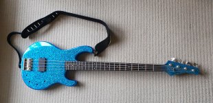
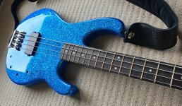
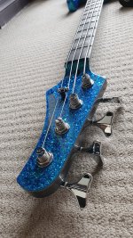
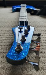
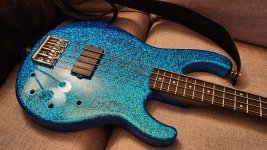
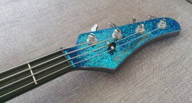
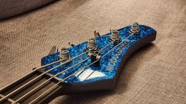
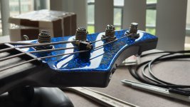
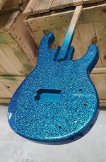
Sure thing, here are some photos of the home made axe haha. It took some time to get it where it is now cause of the huge flakes i used. That's around 10 clear coats or so, then sanded down to smoothness. The actual color is hard to get on camera from these flakes, it's pretty vibrant in person. Bright and open sounding bass, which is what i was after. Those 4 holes are waiting for this electronics, double actually, one opamp and one discreet
Sure thing, here are some photos of the home made axe haha. It took some time to get it where it is now cause of the huge flakes i used. That's around 10 clear coats or so, then sanded down to smoothness. The actual color is hard to get on camera from these flakes, it's pretty vibrant in person. Bright and open sounding bass, which is what i was after. Those 4 holes are waiting for this electronics, double actually, one opamp and one discreet
Attachments
-
 20201123_112410.jpg702.7 KB · Views: 124
 -
 20201123_112511.jpg674.9 KB · Views: 121
 -
 20201123_094213.jpg533.7 KB · Views: 115
 -
 20201123_105141.jpg560.4 KB · Views: 104
 -
 20201123_112600.jpg766.8 KB · Views: 109
 -
 20201123_105854.jpg767.9 KB · Views: 65
 -
 20201122_001108.jpg650.3 KB · Views: 59
 -
 20201121_084643.jpg342.5 KB · Views: 57
 -
 20201123_105703.jpg539.3 KB · Views: 70
 -
 20201123_105730.jpg597.3 KB · Views: 74
Yes, it has ridiculously low current draw but its architecture isn't suited for this application. Anyway in this thread we're working on the discrete preamp with 2x 2N5457, we finished the opamp based one. Thanks for your thoughts thoughDid you consider OPA 196 or 2196 for your application?
Wow! That is spectacular! What a huge time investment .. with a really gorgeous result. 
Still digging for the 'bookmarks' concerning 9V battery life that I had all queued up when we were last working on this. Also botched my secondary plan to have some of my very own '5457s to fiddle with by now. Where-ever does the time go ..?
IIRC JMFahey suggested 400uA as a good target Drain current. I'd venture that he has built many more such devices than I have, so let's run with it. We'll come up with a bias circuit that's reasonably stable over battery voltages from 18 to 14V or so, and that doesn't soak up 164uA just to provide the service. That just seems too wasteful to me since the JFETs aren't consuming any of it.
Seriously - Just Beautiful
Cheers
Still digging for the 'bookmarks' concerning 9V battery life that I had all queued up when we were last working on this. Also botched my secondary plan to have some of my very own '5457s to fiddle with by now.
Where-ever does the time go ..?IIRC JMFahey suggested 400uA as a good target Drain current. I'd venture that he has built many more such devices than I have, so let's run with it. We'll come up with a bias circuit that's reasonably stable over battery voltages from 18 to 14V or so, and that doesn't soak up 164uA just to provide the service. That just seems too wasteful to me since the JFETs aren't consuming any of it.
Seriously - Just Beautiful
Cheers
Last edited:
Could you pls elaborate on this?architecture isn't suited for this application.
X196 series are CMOS, it's the least favorable architecture for audio. Similar for Bipolar, maybe a bit better but both are not the best choice for high impedance, and then FET brings best performance in audio, or sounds most organic or least digitized so to speak. Along that, FET is especially beneficial in high impedance audio due its very high input impedance, in this case instrument amplificationCould you pls elaborate on this?
Wow! That is spectacular! What a huge time investment .. with a really gorgeous result.
Seriously - Just Beautiful
Thanks Rick, glad you like it [emoji1] it does consume a lot time though....probably wouldn't do it again
Still digging for the 'bookmarks' concerning 9V battery life that I had all queued up when we were last working on this. Also botched my secondary plan to have some of my very own '5457s to fiddle with by now.
Do you mean you'll do more simulation?
IIRC JMFahey suggested 400uA as a good target Drain current. I'd venture that he has built many more such devices than I have, so let's run with it. We'll come up with a bias circuit that's reasonably stable over battery voltages from 18 to 14V or so, and that doesn't soak up 164uA just to provide the service. That just seems too wasteful to me since the JFETs aren't consuming any of it.
That sounds very reasonable, it looks like in total we could get around 1mA or so, that would be perfect!
Just please keep in mind that I have the PCB made already by that schematic so mods should be somewhat able to be applied "over" that
There is hardly any valid argument given. Some JFETs are superior devices concerning noise - but if you do the math and consider impedance of your pickups - you will find the differences marginal.X196 series are CMOS, it's the least favorable architecture for audio. Similar for Bipolar, maybe a bit better but both are not the best choice for high impedance, and then FET brings best performance in audio, or sounds most organic or least digitized so to speak. Along that, FET is especially beneficial in high impedance audio due its very high input impedance, in this case instrument amplification
It's not about the arguments as such, it's about the tests done that create the argument. It's the tests that are done over so many years that bring FET as the primary choice for audio. I go with that, I didn't dive in it but there is a reason why it's like that.There is hardly any valid argument given. Some JFETs are superior devices concerning noise - but if you do the math and consider impedance of your pickups - you will find the differences marginal.
Yeah the difference isn't going to be light years, they are all amplifiers and amplify a signal, just some are better for specific usage, like FET's are closest to a "tubey" sound. The difference is small but enough to be a preference for a specific circuit. Also the quality of the architecture plays a role.
Last edited:
Hey Rick, I know you mentioned you're also on another thread, so I don't mean to disrupt that. Was curious if there is a possibility to finish this before NY? It's been sitting on my desk for some time, I've tried several things in meanwhile with not too different results.
You think this is doable?
You think this is doable?
Very short answer: just do it, you have enough good data to work on
The worst options have already been pruned out, those which remain are all reasonable.
Pick one
To help your decision, consider not only "sound" (although obviously this is the primary concern) but practicality, space, parts availability, etc.
Absolute worst case, flip a coin, no "bad" choices remain
Haha that's an interesting way of putting it. Yeah both choices that left sound good, not sure I can hear a difference between the two, but I don't understand the whole dynamics there. Rick is mentioning the dynamic range, that's what confuses me. If I go with the "wider dynamic range" I'm a little higher in battery consumption for a 2 transistor circuit.Very short answer: just do it, you have enough good data to work on
The worst options have already been pruned out, those which remain are all reasonable.
Pick one
To help your decision, consider not only "sound" (although obviously this is the primary concern) but practicality, space, parts availability, etc.
Absolute worst case, flip a coin, no "bad" choices remain
If I go with the good battery life option, then dynamic range is in question... I don't know what I need to hear here I may be missing something, I don't know...
Meanwhile, I have one question if I may. Cause I'm going to use two preamps in the bass and want to save battery of course, I'm switching the power on them along the output via one DPDT switch on the volume pot. This creates a pop audible enough, more or less as loud as the signal.
Has anyone dealt with this before? It's not that practical to lower the volume down on the main amp to switch between the preamps and then bring the volume back up again. I was thinking of adding a calculated value cap in SERIES on the positive power supply. Will this actually delay or smoothen the power-on state on the preamp? Will it work at all or maybe mess with the preamp or the sound? Don't really want to experiment before I get some thoughts on it.
I'm immensely thankful, people have been so helpful and nice and I've asked so many questions I'm about to feel ashamed.
A capacitor in series with a DC voltage source will eventually (after it is charged) shut down the supply completely.
Why don't you use a TRS type phone socket in your guitar with the negative battery lead connected to the ring lug? This also avoids the possibility that your batteries are getting discharged it you forget to trip the on-off switch.
And it's always been good practice to first plug the cord into the guitar, then connect it to the amp. Otherwise you may get nasty noise even with a passive, unpowered instrument.
Best regards!
- Status
- This old topic is closed. If you want to reopen this topic, contact a moderator using the "Report Post" button.
- Home
- Live Sound
- Instruments and Amps
- Bass guitar FET preamp