To reduce RF pickup try a small bypass cap across the input. Try 100pf ceramic eg.
Will try this, thanks for the tip cbdb!
Hey Rick, have you had some spare time to have a look at the measurements above.. how does that look?
I'm still here 😉 .. lost in other pursuits again!
Gotta come up with some better techniques for keeping up -- EVEN WHEN this Chrome browser takes a dive and torches all my tabs ..
Thanks for being so patient. I'll get after it by this time tomorrow ..
Cheers
Gotta come up with some better techniques for keeping up -- EVEN WHEN this Chrome browser takes a dive and torches all my tabs ..
Thanks for being so patient. I'll get after it by this time tomorrow ..
Cheers
Good to hear you're still here, thanks for helping out this much [emoji16]
I know, happened to me with chrome as well, especially after an update.
OK sounds good, seems like we're almost there
I know, happened to me with chrome as well, especially after an update.
OK sounds good, seems like we're almost there
OK -- thanks for the voltages .. now we're getting somewhere. I'm starting to suspect a couple of things may be going on, and part of the challenge is, that they're interactive ..
- any change to the Source resistors will change power consumption
- high performance and low power consumption are usually enemies -- if you lower the Source resistor, you must lower the bias divider voltage, or the current demand will increase
- Aguilar may be deliberately *using* the asymmetric 'compression'(*). Could be why discrete FET's were chosen: At a time when op-amps can be as cheap as transistors and often require fewer supporting components, either Design or Marketing needs to furnish a pretty good reason for the added expense. It might also partially explain the choice of identical bias on successive stages (or each stage uses a different *selected* transistor), since each stage would 'smoosh' the opposite half of the waveform.
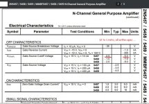
- your transistors are different than Aguilar's; odds are they bought 5 or 10 thousand from as many production lots as possible, then selected the ones meeting their Idss and Vgs(off) requirements (see included PDF excerpt); latter spec can be anywhere within a 12:1 range(!), and sets the operating point
- your pickups are not Aquilar; we're trying to adapt a design that seems to be pretty cleverly designed, from the ground up, for a very different pickup; If the same designer were tasked with designing for the pickup(s) you're using, a completely different design might result.
I don't think I realized that you owned an Aguilar preamp! Is it encapsulated, or could you take some measurements on it? Current draw at 9 and 18V would be a great place to start. Then Drain voltage of each stage would also be revealing (at 18V-only would be fine).
If you still have the trimpot in the bias divider, good; but I want to confirm how it's wired. Better to have the 100k applied to the CW terminal, ground the CCW terminal, and take bias from the wiper -- makes for much simpler arithmetic. At 1,48V currently, R2 must be 8959 ohms (assuming 18V supply); let's move that R1 leg from the wiper to the CW terminal.
Assuming I'm not choking on the math, we should be able to get excellent dynamic range and better all-around performance on a miserly current draw of about 2 mA:
164 uA - bias divider -- 18V / 110k ohms
0,8 - 0,9 mA - per transistor; finding a Source resistor / bias point combination that produces 9 to 10V on the Drains
Right now you only have about a volt and a half peak-to-peak of output swing. Getting the quiescent Drain voltage closer to the middle of the supply will be a major improvement.
Don't worry about the questions -- they're all good.😉 But I wouldn't mind talking you out of changing one thing at a time, finding some performance attribute objectionable, then discarding it to try something else. This seemingly straight-forward design has a fair bit of subtlety built in, and begs for a more comprehensive approach.
* Asymmetric compression, AKA 'soft clipping', AKA 'tube sound' is the rounding/flattening/smooshing of one side/half of the waveform that results when the FET is straining to turn off (as far as the Gate terminal says it should), but the Drain resistor has so little voltage across it that very little current is available to yank up on the Drain.
Cheers
- any change to the Source resistors will change power consumption
- high performance and low power consumption are usually enemies -- if you lower the Source resistor, you must lower the bias divider voltage, or the current demand will increase
- Aguilar may be deliberately *using* the asymmetric 'compression'(*). Could be why discrete FET's were chosen: At a time when op-amps can be as cheap as transistors and often require fewer supporting components, either Design or Marketing needs to furnish a pretty good reason for the added expense. It might also partially explain the choice of identical bias on successive stages (or each stage uses a different *selected* transistor), since each stage would 'smoosh' the opposite half of the waveform.
- your transistors are different than Aguilar's; odds are they bought 5 or 10 thousand from as many production lots as possible, then selected the ones meeting their Idss and Vgs(off) requirements (see included PDF excerpt); latter spec can be anywhere within a 12:1 range(!), and sets the operating point
- your pickups are not Aquilar; we're trying to adapt a design that seems to be pretty cleverly designed, from the ground up, for a very different pickup; If the same designer were tasked with designing for the pickup(s) you're using, a completely different design might result.
I don't think I realized that you owned an Aguilar preamp! Is it encapsulated, or could you take some measurements on it? Current draw at 9 and 18V would be a great place to start. Then Drain voltage of each stage would also be revealing (at 18V-only would be fine).
If you still have the trimpot in the bias divider, good; but I want to confirm how it's wired. Better to have the 100k applied to the CW terminal, ground the CCW terminal, and take bias from the wiper -- makes for much simpler arithmetic. At 1,48V currently, R2 must be 8959 ohms (assuming 18V supply); let's move that R1 leg from the wiper to the CW terminal.
Assuming I'm not choking on the math, we should be able to get excellent dynamic range and better all-around performance on a miserly current draw of about 2 mA:
164 uA - bias divider -- 18V / 110k ohms
0,8 - 0,9 mA - per transistor; finding a Source resistor / bias point combination that produces 9 to 10V on the Drains
Right now you only have about a volt and a half peak-to-peak of output swing. Getting the quiescent Drain voltage closer to the middle of the supply will be a major improvement.
Don't worry about the questions -- they're all good.😉 But I wouldn't mind talking you out of changing one thing at a time, finding some performance attribute objectionable, then discarding it to try something else. This seemingly straight-forward design has a fair bit of subtlety built in, and begs for a more comprehensive approach.
* Asymmetric compression, AKA 'soft clipping', AKA 'tube sound' is the rounding/flattening/smooshing of one side/half of the waveform that results when the FET is straining to turn off (as far as the Gate terminal says it should), but the Drain resistor has so little voltage across it that very little current is available to yank up on the Drain.
Cheers
Attachments
Forgot to mention -- if the 2mA battery draw is too much for your taste, a very slight impedance increase would be my first choice for a compromise. It would only slightly affect the curves of the tone stack, and wouldn't appreciably reduce the cable-driving ability while maintaining the output-swing / dynamic-headroom.
Regards
Regards
Last edited:
Ok, for some reason i didn't get a notification on Tapatalk for your post... there is almost always one but now none.. I just see this, sorry about that.
I'm going to go though this carefully over the weekend and re-read your post to understand it a bit better, and try the things that you mentioned in the next several day, take some measurements and post them here. I'm guessing this is with both caps removed? Without them I did get the current to about 2.2-2.3mA a few weeks ago, which sounded pretty good also, maybe a bit tighter/stiffer than with one cap in, but even with one cap sounds very unique and it works very well on bass, probably that is the "one sided tube like" ultra soft clipping or assymetric compression. I got a Delano MM HE pickup btw.
Could be different transistors, or they bought thousands of them and picked the ones that best fit the circuit. Anyway, we'll try to work with what we have, i got 10 more so i'll measure those. What is an accurate but simple way to measure them?
The bias trim is still there, not sure if i can swap the legs though, i got the PCB factory made already, I'll try to work it out as it is, i guess that won't be the biggest issue...
So if we need to get the current that high to make this where it should be then be it. I just though it was a bit too high for transistor driven preamp but don't mind me, i'm only familiar with some stuff here.
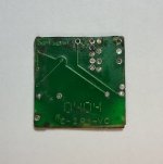
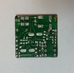
Yes i do own the Aguilar OPB-1 which is this circuit more or less, unforutnately it's not here with me in Australia, so i can't test anything �� And it's encapsulated in rock solid black epoxy. The only thing that i found is that some guy decided to completely destroy it to get inside and i only have a photo of the PCB. I'll attach it below but not sure it will be of any help, it's bare PCB.
Let me know if you get something interesting in meanwhile. This is both fun and "what the hell do we do now to get this but also to retain this".. ��
I'm going to go though this carefully over the weekend and re-read your post to understand it a bit better, and try the things that you mentioned in the next several day, take some measurements and post them here. I'm guessing this is with both caps removed? Without them I did get the current to about 2.2-2.3mA a few weeks ago, which sounded pretty good also, maybe a bit tighter/stiffer than with one cap in, but even with one cap sounds very unique and it works very well on bass, probably that is the "one sided tube like" ultra soft clipping or assymetric compression. I got a Delano MM HE pickup btw.
Could be different transistors, or they bought thousands of them and picked the ones that best fit the circuit. Anyway, we'll try to work with what we have, i got 10 more so i'll measure those. What is an accurate but simple way to measure them?
The bias trim is still there, not sure if i can swap the legs though, i got the PCB factory made already, I'll try to work it out as it is, i guess that won't be the biggest issue...
So if we need to get the current that high to make this where it should be then be it. I just though it was a bit too high for transistor driven preamp but don't mind me, i'm only familiar with some stuff here.
Yes i do own the Aguilar OPB-1 which is this circuit more or less, unforutnately it's not here with me in Australia, so i can't test anything �� And it's encapsulated in rock solid black epoxy. The only thing that i found is that some guy decided to completely destroy it to get inside and i only have a photo of the PCB. I'll attach it below but not sure it will be of any help, it's bare PCB.
Let me know if you get something interesting in meanwhile. This is both fun and "what the hell do we do now to get this but also to retain this".. ��
Attachments
Last edited:
- high performance and low power consumption are usually enemies -- if you lower the Source resistor, you must lower the bias divider voltage, or the current demand will increase
I think i'm somewhat on point with this. By your estimation/calculation in this and previous posts you were pretty much spot on - about 1.85k source resistors each and 10k bias trimmer setting is what works as "best optimized" without the caps in.
- Aguilar may be deliberately *using* the asymmetric 'compression'(*). Could be why discrete FET's were chosen
Damn i don't have the Aguilar here with me to compare power consumption and if there is any deliberate compression, if i remember correctly i think there isn't a compression. But anyway, that compression does sound pretty interesting i must say.I don't think I realized that you owned an Aguilar preamp! Is it encapsulated, or could you take some measurements on it? Current draw at 9 and 18V would be a great place to start. Then Drain voltage of each stage would also be revealing (at 18V-only would be fine).
If you still have the trimpot in the bias divider, good; but I want to confirm how it's wired. Better to have the 100k applied to the CW terminal, ground the CCW terminal, and take bias from the wiper -- makes for much simpler arithmetic. At 1,48V currently, R2 must be 8959 ohms (assuming 18V supply); let's move that R1 leg from the wiper to the CW terminal.
Assuming I'm not choking on the math, we should be able to get excellent dynamic range and better all-around performance on a miserly current draw of about 2 mA:
164 uA - bias divider -- 18V / 110k ohms
0,8 - 0,9 mA - per transistor; finding a Source resistor / bias point combination that produces 9 to 10V on the Drains
Your math is very in point, i got this with gain of 1:
- About 9.85V on each transistor
- 1.85k source resistor on each transistor
- 10k bias trimmer setting
- and 1.78mA total power consumtion
I think this is what you're talking about.. ?
The only audible difference between this and the previous combination with 1 cap is the compression. With these components, the cap out and more power consumption the slight compression is gone. I think that's the only thing I can hear that is different, isn't a huge difference but enough to tell the deifference. It's funny that both sound good.
Ok, I got the voltage here at about 9.85V. Other than the compression i don't know if this peak to peak is something audible or not, could you explain this to me please? I googled it but I don't understand the explanation as i should i thinkRight now you only have about a volt and a half peak-to-peak of output swing. Getting the quiescent Drain voltage closer to the middle of the supply will be a major improvement.
Oook now i understand what that compression is... Rick, the explanations you give me I find them very on point and easy to understand, can't say thank you enough for that 🙂* Asymmetric compression, AKA 'soft clipping', AKA 'tube sound' is the rounding/flattening/smooshing of one side/half of the waveform that results when the FET is straining to turn off (as far as the Gate terminal says it should), but the Drain resistor has so little voltage across it that very little current is available to yank up on the Drain.
It seems like at the end the problem will be deciding whether to keep the compression with very power consumtion or keep the clean cause both sound good xD...oh man haha. But i have several PCB's so maybe I can make both...
Last edited:
.. have several PCB's so maybe I can make both ..
I like that idea -- any chance there's room in the bass for all 3 preamps ?😉
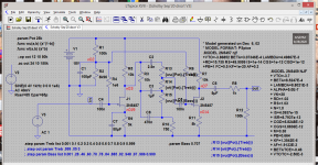
Some very interesting things have turned up playing with this circuit in LT Spice (besides that I'm not very good with it!😱). Here are some of the discoveries so far . .
- the transistors originally fitted are 'not very conductive'; according to LT Spice and the admittedly poor model, your Drains should be around 10 or 10-1/2 volts
- none of the combinations of bias voltage / Source resistance (collectively: 'operating point') / supply voltage (that I've tried) can produce the results you have so far
- when your 10 new transistors come in, we might want to devise a not-too-difficult-to-implement test to select a couple that might be more suitable
- if you keep the two first fitted we should bump up the Drain resistances - maybe 15, 18 or 22k; if I can figure out how to fiddle the 2N5457 model I have (or somebody on here tells me), I might be able to figure how much. It'd probably be good to simulate it first 'cause it'll almost certainly affect the response curves, which are already a little odd.
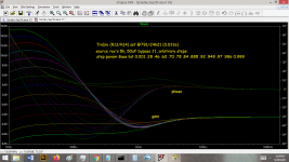
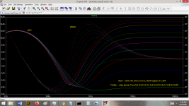
- The tone stack is producing a large dip, an octave or two wide, varying from 200 to 400 Hz. It may be exactly what you want. But if it were me I'd much rather apply it intentionally with an EQ, than to have it as an inescapable side effect of the tone controls. Especially since it varies in both depth and center frequency as they do.
The 'op point' file has some interesting data. Admittedly, sorting useful bits out of it is quite a challenge even with the LT Spice screen for the node references. But it does show a couple of options that only consume 1.2 and 1.7mA, so it is definitely possible to lower the battery drain.
Have a look at the FR curves. If I still have a minute before I upload this stuff I'll go back and annotate a few nodes (on the JPG of the LT Spice screen shot).
There's still a lot to simulate concerning the operating point; so far most of the sims have been using the 5k Source resistors and 1,48V bias divider. I'm pretty sure that is not optimum.
Cheers
Attachments
-
 Schotky Sep'20 discrt V3 LTSpc.png138.5 KB · Views: 769
 -
 Schotky Sep'20 discrt V3-50uF-J1-byp,Bass-arbitrary-step.png147.1 KB · Views: 262
 -
 Schotky Sep'20 discrt V3-Treb,50uF-J1-bypass.png143 KB · Views: 166
 -
Schotky Sep'20 discrt V3.zip407 KB · Views: 95
-
Schotky Sep'20 discrt, op points.txt6.8 KB · Views: 103
Haha, well there's definitely enough room for 2, and that's the unplanned plan now since the opamp one turned out so good 🙂I like that idea -- any chance there's room in the bass for all 3 preamps ?😉
These measurements sometimes confuse me, i don't know why.... so multimeter probes - one to GND the other on Drain (pin 1 on transistor) reads about 9.85V, i guess that's the drain voltage.....Some very interesting things have turned up playing with this circuit in LT Spice (besides that I'm not very good with it!😱). Here are some of the discoveries so far . .
- the transistors originally fitted are 'not very conductive'; according to LT Spice and the admittedly poor model, your Drains should be around 10 or 10-1/2 volts
One probe to GND and the other on Source (pin 2 on the transistor) I couldn't get it more than about 1.7V....
Sorry if I have messed something here up
This may have been due to my poor measurements darn it, my fault if I gave you wrong information for which I didn't know it was wrong :/- none of the combinations of bias voltage / Source resistance (collectively: 'operating point') / supply voltage (that I've tried) can produce the results you have so far
I got them a few days ago, labeled as Fairchild, hopefully are genuine but who knows.- when your 10 new transistors come in, we might want to devise a not-too-difficult-to-implement test to select a couple that might be more suitable
What is the test?
Ok, right now i have 20k trimmers on Source, i can put 20-25k trimmers on Drain too. What will we get if we bump them up?- if you keep the two first fitted we should bump up the Drain resistances - maybe 15, 18 or 22k; if I can figure out how to fiddle the 2N5457 model I have (or somebody on here tells me), I might be able to figure how much. It'd probably be good to simulate it first 'cause it'll almost certainly affect the response curves, which are already a little odd.
I think that tone stack (it's a Fender tone stack btw) is meant to function that way, the dip even matches the frequencies shift 200-400Hz you mention. When you adjust Bass/Treble, the mid scoop shifts its frequency a little. It sounds really good on bass though. I don't know how much effort there is to make this "on purpose" as you say, but we can leave it as is if too much time will take to get the same result actually, i don't know how this is done 🤔. If you use Duncan's Tone Stack Calculator, under Fender tab it will give you a nice simulation of the tone stack only. Below i have attached the Tone Stack Calculator file settings for Fender tone stack. Give it a check.- The tone stack is producing a large dip, an octave or two wide, varying from 200 to 400 Hz. It may be exactly what you want. But if it were me I'd much rather apply it intentionally with an EQ, than to have it as an inescapable side effect of the tone controls. Especially since it varies in both depth and center frequency as they do.
Ok, so now i'm getting 1.78mA current draw, both Source caps out with Source resistors 1.8k each and bias trimmer at ~10k.The 'op point' file has some interesting data. Admittedly, sorting useful bits out of it is quite a challenge even with the LT Spice screen for the node references. But it does show a couple of options that only consume 1.2 and 1.7mA, so it is definitely possible to lower the battery drain.
(Another thing that I noticed with more testing depending on time of day I test - with one Source cap in the circuit, it can catch some radio signal, very weak but audible on loud volume with no input signal, and sometimes not. But with both Source caps out the circuit it's quiet as hell, no RF at any time of day or any weird noise! This was tricky to figure out though..)
The curves looks somewhat similar what the Tone Stack Calculator produces, check the settings file i've attached and see how it looks. It's only the tone circuit though, not the whole preamp.Have a look at the FR curves. If I still have a minute before I upload this stuff I'll go back and annotate a few nodes (on the JPG of the LT Spice screen shot).
One thing though, I see you've put the Source cap in the first stage. When I do this in the circuit i'm getting distorted sound no matter the Source resistance or bias value. When I put the cap in the second stage, it sounds normal..... then, the resistor value in the second stage is about 5k with the cap in, and in the first stage the resistor is about 10k (no cap). This sounds pprobably at least 95% the same as with both Source caps out just much lower current draw. Less than 0.7mA. The only drawback is the frickin random RF, barely audible but randomly present.There's still a lot to simulate concerning the operating point; so far most of the sims have been using the 5k Source resistors and 1,48V bias divider. I'm pretty sure that is not optimum.
Since at this point it sounds pretty good (it's hard to describe how it sounds you may find something wrong with it but I don't think I can say there's something missing in the sound it can give), should we fiddle around more with the tone response or just focus on lower current draw... maybe you'll have a better idea after you see the Duncan's Tone Stack Calcuclator simulation and compare it to LTSpice.. So where do we start?
Attachments
These measurements sometimes confuse me, i don't know why.... so multimeter probes - one to GND the other on Drain (pin 1 on transistor) reads about 9.85V, i guess that's the drain voltage.....
Yes -- correct!
.. and ..One probe to GND and the other on Source (pin 2 on the transistor) .. 1.7V....
Sorry if I have messed something here up ..
This may have been due to my poor measurements ..
No need to apologize! You're doing just fine. Your multimeter may owe both of us an apology, though.😉 Is it, perhaps, Analog(?OMG!), and only a few Kohms/volt?😱
We didn't go into the reasoning behind measuring the bias divider directly instead of a the FET Gate -- the meter was loading the measurement! When you measure the Drain voltage, part of the current to ground is being provided by the meter. The giveaway is if the measurement changes when you change ranges (because it changes loading on the circuit). The Gate is much higher impedance so the effect is worse. But in this circuit the Source and Drain currents are only a few hundred micro-amps, so there is still corruption.
requote:
Also not your fault at all! I didn't put it properly. All that meant was, the model used for simulation behaves differently than the transistor in the circuit.- none of the combinations of bias voltage / Source resistance ..
If you really have 9.85V on the Drain, that's plenty close to optimum. But it'll surprise me if it is. Can you try measuring it on a higher-voltage range?
As far as the new transistors go, we'd better leave those aside for now. They'll only introduce more variables unless/until we can measure more accurately. And please, no more trimpots -- I LOVE the little stinkers, and have used many over the years. But the variables go up exponentially once you have several, quickly exceeding my ability to analyze and respond back. (You seem to be a much faster, more efficient writer than me.😉)
The only reason to consider the higher Drain resistors was when we thought there were only 1,56 and 2.92 volts across the 10k parts. Those are currents of 156 and 292 micro-amps if we ignore what additional load the meter may contribute. Either way it implies 'too high source resistance'. If we kept that it would have meant higher output impedance and lost dynamic range.
The bypass cap on the 1st stage was only to see how close LT Spice could get to the results you were describing. I don't (and hadn't intended to) recommend it/them. The 1st stage distortion is likely a combination of higher gain and lower operating current (Source resistors 5 and 10k at the time IIRC).
The RF leakage should be eliminated by a small capacitor from Source to Gate of the 1st stage; 100 or 150pF would work. Not my idea, but it's a good one.
My Windows 8.1 wouldn't open your ZIP; not sure if I'll get a chance to lookup Duncan's Tone Stack Calculator, but if you're happy with the tone it's fine with me. Were you able to unZIP the junk I sent?
The thing to remember about the Source resistor value is, the current through the Drain resistor will be identical. Matching resistors will produce matching signal swings 180 degrees out of phase -- a unity gain buffer, or inverter, depending on which leg you take the signal from. Lower value Source resistors are a must to produce gain.
Let's try fitting a fixed resistor for each Source, 1k5 (16,5dBV gain) to 2k7 (11,4dBV gain), setting the bias in the 0,35 to 0,8V neighborhood, fit the small cap Gate to Source on the 1st stage, and see if it gives acceptable performance and power drain.
I'll keep fiddling the simulator model.
Regards
Yes -- correct!
Good to know that that's correct, thanks!
Oh damn I'm done with the analogs a long time ago finally.. this one is digital but of the cheaper onesNo need to apologize! You're doing just fine. Your multimeter may owe both of us an apology, though.😉 Is it, perhaps, Analog(?OMG!), and only a few Kohms/volt?😱
Oh ok then, from the simulation graphs maybe it isn't too far from the actual circuit but that's only compared to the response curves from the Tone Stack Calculator. If you want to check out the simulator, I've reattached the Calculator software with the settings file to save you some time searching for it. it's actually a .rar file instead of .zip, but renamed it as this forum doesn't accept rars. Download it, rename the file extension from .zip to .rar and you should be able to unpack it. It's a relatively quick installation, when you run the Calculator just open the settings file and it's very straight forward to use.requote:
Also not your fault at all! I didn't put it properly. All that meant was, the model used for simulation behaves differently than the transistor in the circuit.
It is really 9.85V, i've gone up to about 14.5V with no audible change except slight change in gain.If you really have 9.85V on the Drain, that's plenty close to optimum. But it'll surprise me if it is. Can you try measuring it on a higher-voltage range?
The RF leakage should be eliminated by a small capacitor from Source to Gate of the 1st stage; 100 or 150pF would work. Not my idea, but it's a good one.
I have put 100p on both stages, it eliminated the RF by at least 95%. With even more testing (the Source trimmers are hanging on a 10cm long wire though) I accidentally discovered that the trimmer's wires are the antenna of the circuit... I touched one of them and the radio signal got boosted by probably 5x! On the radio they said that Australia is very different in dating than the rest of the world... interesting info I think they're right xD, damn it was a litteral radio receiver. When I put resistors in instead of the trimmers I guess the rest 5% will go away too cause there will be no wires to the resistors to pickup RF.
My Windows 8.1 wouldn't open your ZIP; not sure if I'll get a chance to lookup Duncan's Tone Stack Calculator, but if you're happy with the tone it's fine with me. Were you able to unZIP the junk I sent?
Yes I like the tone so we can leave it as is. I've attached the Calcuclator though for you if you want to check it out, this one is very simple to operate, just follow the instructions i described above to unpack the file.
We didn't go into the reasoning behind measuring the bias divider directly instead of a the FET Gate...
The only reason to consider the higher Drain resistors was when we thought there were only 1,56 and 2.92 volts across the 10k parts...
The thing to remember about the Source resistor value is, the current through the Drain resistor will be identical....
Very good info, thanks for that!
Let's try fitting a fixed resistor for each Source, 1k5 (16,5dBV gain) to 2k7 (11,4dBV gain), setting the bias in the 0,35 to 0,8V neighborhood, fit the small cap Gate to Source on the 1st stage, and see if it gives acceptable performance and power drain.
Ok, tried this too. Fitting the cap on the 1st stage produces unusable results. Lots of distortion and compression regardless of the bias or source resistor value, i went all the way through. If i have the the Source resistors 1k5-2k7 and having the cap fitted, the gain is enormous, volume on the amp set to 0 and i could still hear the signal, i'm not even joking...
BUT, having the cap in the 2nd stage and source resistors 5k and 10k, drain voltages 16.4V and 14.9V not sure if it's good in theory but no issues in practice (this consuming 0.6-0.7mA), and then no source cap and both source resistors about 1k8, drain V both 9.85V (this consuming about 1.8mA) - if you would blind fold me I don't think I would be able to tell the difference between the two, noise, tone response and gain all included. The one with the cap drawing 1.1mA less current which is significant difference I can say for a situation where there is pretty much no audible difference...
I know you are against having the caps especially in the 2nd stage and it couldn't make more sense, but I can't really hear any difference, even that "slight compression" that I thought it was there (probably there isn't at all, after so much testing my head is upside down) it seems like just the circuit is like that but does sound good on bass. And having the cap in first stage distorts no matter the component values. If the cap variant affects the dynamic range, probably it isn't within a bass guitar range too, I don't know.. Thoughts?
Last edited by a moderator:
I'm not actually *against* anything -- it's your project, after all. You should build it as you see fit -- exactly the way YOU want it! I'm only here to advise on the tradeoffs.
We may have a 'failure to communicate' on the capacitor issue. I'm not still talking about Source bypassing -- that was only to get a decent estimation of the behavior/performance you were reporting. Please put all thoughts of that aside. The cap mentioned in post 52 was to be connected Source-to-Gate on the first stage, is over 5 orders of magnitude smaller, and affects only RF gain.
Found a simulator model that seems to more closely resemble your FET's. (Yay!) Still have some testing loose ends to tie up, but so far I can safely suggest ..
- remove all 3 trimpots
- fit 1k8 or 2k2 fixed resistors in each Source leg; use leaded parts if necessary
- connect the free end of the bias 1 meg resistors to ground
- fit a 100pF to 220pF ceramic capacitor, Gate-to-Source on the 1st stage
- measure the Drain voltages with power applied, both 18V and 9V
- measure the Source voltages, same as Drain
- measure the current draw
Then we'll do some arithmetic to confirm how trustworthy the values are. (Remember, the S and D currents are identical -- the voltage drop must be proportional to the respective resistances. It should also be reasonably close to the same current draw at 9V as at 18V.
If it looks like meter loading is still a problem, we'll devise a buffer -- either using one of the batch of new transistors, or use the 2nd stage (to measure the 1st).
It's terrific that you're happy with the sound. Sometimes that's the hardest part. But I also sure know what you mean about 'having done so much listening' that it's hard to remember what you've heard.😉
Also, was able to draw down my very own copy of Duncan's tone stack tool. Very neat. But if I read his legal notice correctly, we're not supposed to disseminate the tool ourselves. You might want to ask a moderator to 'unpost'/'de-list' your last attachment, just to stay proper.😉
One thing I forgot to include in post 52 was, 'How are you measuring the battery current?'
Regards
Ooh, ooh -- almost completely forgot ..
And remember that useful lesson about the trimpot-wire-antenna! We all have them 😱, and they always come in handy again someday ..
Cheers
And remember that useful lesson about the trimpot-wire-antenna! We all have them 😱, and they always come in handy again someday ..
Cheers
That's what i meant 🙂I'm not actually *against* anything -- it's your project, after all. You should build it as you see fit -- exactly the way YOU want it! I'm only here to advise on the tradeoffs.
We may have a 'failure to communicate' on the capacitor issue. I'm not still talking about Source bypassing -- that was only to get a decent estimation of the behavior/performance you were reporting. Please put all thoughts of that aside. The cap mentioned in post 52 was to be connected Source-to-Gate on the first stage, is over 5 orders of magnitude smaller, and affects only RF gain.
Found a simulator model that seems to more closely resemble your FET's. (Yay!) Still have some testing loose ends to tie up, but so far I can safely suggest ..
- remove all 3 trimpots
- fit 1k8 or 2k2 fixed resistors in each Source leg; use leaded parts if necessary
- connect the free end of the bias 1 meg resistors to ground
- fit a 100pF to 220pF ceramic capacitor, Gate-to-Source on the 1st stage
- measure the Drain voltages with power applied, both 18V and 9V
- measure the Source voltages, same as Drain
- measure the current draw
Did that and results are:
On 18V:
- current draw: starts at 0.4mA and then stabilises to 0.23 in about 20-30 sec
- D voltages: 16.8V on both
- S voltages: 0.2V on both
On 9V:
- current draw: starts at 0.25mA and then stabilises to 0.18V in also about 20-30 sec
- D votages: 8.1V on both
- S voltages: 0.14V on both
Sound vise: clips and compressed, not a lot but is clealry audible, something like a staring level of an overdrive. With 1k8 S resistors gain is a little less than 1.
Got itThen we'll do some arithmetic to confirm how trustworthy the values are. (Remember, the S and D currents are identical -- the voltage drop must be proportional to the respective resistances. It should also be reasonably close to the same current draw at 9V as at 18V.
We can use one fo the new batch, not a problem. Also, what is a good way to match them? I'm not sure the one way I used before is very accurate. But if matching isn't necessary for this circuit then we're good. IF it is, i'd want to do that while we're working on the main bit.If it looks like meter loading is still a problem, we'll devise a buffer -- either using one of the batch of new transistors, or use the 2nd stage (to measure the 1st).
Damn I didn't even think of that, very good reminder! I know it's free but forgot there could be "share" limits. I'll try to reach to moderators to remove the attachment.Also, was able to draw down my very own copy of Duncan's tone stack tool. Very neat. But if I read his legal notice correctly, we're not supposed to disseminate the tool ourselves. You might want to ask a moderator to 'unpost'/'de-list' your last attachment, just to stay proper.😉
The current the circuit draws? Multimeter in series with the batteries and the circuitOne thing I forgot to include in post 52 was, 'How are you measuring the battery current?'
Indeed 😀And remember that useful lesson about the trimpot-wire-antenna! We all have them, and they always come in handy again someday ..
Last edited:
Just noticed a few minor errors in the post above, fixed in red:
On 18V:
- current draw: starts at 0.4mA and then stabilises to 0.23mA in about 20-30 sec
- D voltages: 16.8V on both
- S voltages: 0.2V on both
On 9V:
- current draw: starts at 0.25mA and then stabilises to 0.18mA in also about 20-30 sec
- D votages: 8.1V on both
- S voltages: 0.14V on both
On 18V:
- current draw: starts at 0.4mA and then stabilises to 0.23mA in about 20-30 sec
- D voltages: 16.8V on both
- S voltages: 0.2V on both
On 9V:
- current draw: starts at 0.25mA and then stabilises to 0.18mA in also about 20-30 sec
- D votages: 8.1V on both
- S voltages: 0.14V on both
....I know it's free but forgot there could be "share" limits. I'll try to reach to moderators to remove the attachment....
A particular point is that Duncan publishes updates and may not want "old" versions hanging around the interwebs like the old lawnmower behind my garden shed.
To get a moderator's attention quickly but politely, click the triangle "!" icon lower right of the problematic message. Say like "This is my message, but I need the file attachment/link removed for a reason". I've picked-up the link for *your* message:

https://www.diyaudio.com/forums/report.php?p=6359005
A particular point is that Duncan publishes updates and may not want "old" versions hanging around the interwebs like the old lawnmower behind my garden shed.
To get a moderator's attention quickly but politely, click the triangle "!" icon lower right of the problematic message. Say like "This is my message, but I need the file attachment/link removed for a reason". I've picked-up the link for *your* message.
That is a valid point too. I've requested the removal of the attachment.
Well, thanks for that PRR, I very appreciate the gesture 🙂
Hey Rick, not rushing you I know you also have your own stuff too, so just asking. Do you think we would be able to finalize this in about a week?
I'm about to start painting the bass in about that much time, so once I start that I won't be able to do any audio tests on a bass for about a month or so..
I'm about to start painting the bass in about that much time, so once I start that I won't be able to do any audio tests on a bass for about a month or so..
- Home
- Live Sound
- Instruments and Amps
- Bass guitar FET preamp