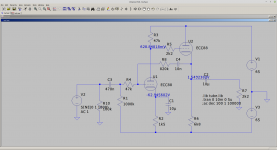
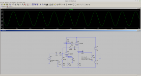
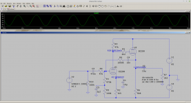
R9 and C5 to stop noise getting in from the negative supply through the 470k into the grid and being amplified. R1 to make sure the grid has a path to the negative supply so the first stage is biased wrt to the negative rail to give enough voltage. C1 again coupled to ground to stop the negative supply coupling between grid and cathode. R10 to stop any initial neagative voltage damaging the stage before as C3 charges.
R9 and C5 don't have much effect actually you could just make R9 say 1M and no C5. Its also better moved to the input. C1 coupled to -negative rail has a very big effect coupling the signal in.

R9 and C5 don't have much effect actually you could just make R9 say 1M and no C5. Its also better moved to the input. C1 coupled to -negative rail has a very big effect coupling the signal in.

Last edited:
I had thought about using a transformer. I'm using a Jensen JT-11P-1 in a FirstWatt F5 Turbo amp I built. I'm not really happy with the sound on that amp, but not sure if that's due to the transformer, pre-amp drive capability, or something else. But finding the Jensen in a PCB mounted version was very challenging. I ended up getting used ones off ebay, so I appreciate the link to Sowter. I wasn't familiar with them.
I've got this crazy idea to build both a ultra-low distortion op amp buffer and a common cathode tube stage, then use a balance pot to blend the two so I can adjust the amount of "tube sound" I want to use.
So I'd have a differential receiver, and could drive the tube stage with a single ended signal, and convert back to balanced after my balance control. I'd have to match the gain of the two paths, and probably have to adjust for overall gain between the two channels, but it seems like this could be interesting.
Do you think it makes sense to use a CCS on the 12B4 (which I assume would improve power supply rejection), or would I get more of the tube sound (even harmonics) using just resistor loading?
Rongon and Baudoin0 - sorry I didn't noticed there was an additional page on the thread and didn't see your posts before my last reply. Thanks for the schematic. Is the second state necessary if I'm driving a high impedance buffer stage?
On #1 you said you were driving 2k2. Thats why its there. Yes you can remove it and put the fb from the plate of U1. The ECC88 has two valves in one and I believe you are using separate PCB's for left and right it does not make any difference having the buffer. Having the buffer means you don't need the op-amp driver.
Do not forget output delay of the tube stage. Or else you blow your amp and speakers when you turn on the tubepreamp and class D combo. When the tube is start heating there will be a lot of DC voltage at the output of the tubepreamp.
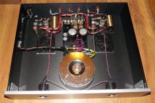
Build a lot of tube preamps for hypex oem modules.
Build a lot of tube preamps for hypex oem modules.
Attachments
Thanks. That's what I assumed. I need a balanced signal to drive the Purifi module, and if I implement my parallel buffer scheme described in post #45, I'd follow the balance pot with a differential driver anyway. But I assume that reducing the load on the cathode of U2 won't have any downsides.
Either way, this looks like a nice design and I appreciate you taking the time to model it. It looks like you are providing some high frequency NFB through R8/C4. Is this to improve stability?
On another topic, I just installed LTSpice and am trying to learn how to use it. Are you using a generic tube model and specifying parameters? Or is there a model available for the ECC88?
Thanks,
Jay
@Koifarm - Thanks for the reminder. That looks like a nice build. Are you using a relay on a delay timer to connect the tube buffer to the Hypex module?
Re: LTspice -
There are no generic tube models but there's a thread right here on diyAudio that is *the* place to get models for all kinds of tubes.
Vacuum Tube SPICE Models
--
There are no generic tube models but there's a thread right here on diyAudio that is *the* place to get models for all kinds of tubes.
Vacuum Tube SPICE Models
--
ltspice is available free. diyaudio has all the tube models to download. Its a good way to learn. I can send you .asc file.
@baudouin - wow, that would be much appreciated. I've installed ltspice, but have only had time to play with it for 10 minutes or so. I have a LOT to learn about it.
Super. I don't see much advantage driving the module differential it needs 10Vrms for full output so I really don't think you will have a noise problem. Just make sure you return the -ve input back to the ground on the pre-amp.
I don't think you will need a mute relay - the module will be AC coupled to the pre-amp and on turn on the voltage will change gradually (after an initial click) so there won't be much voltage change. The module has a turn on delay and DC protection of the speakers so it looks like its all done for you.
I don't think you will need a mute relay - the module will be AC coupled to the pre-amp and on turn on the voltage will change gradually (after an initial click) so there won't be much voltage change. The module has a turn on delay and DC protection of the speakers so it looks like its all done for you.
Last edited:
Oops!
So the tube line stage needs to swing 10Vrms into the 2.2k ohm input impedance presented by the power amp module inputs? That's a horse of a different color there...
That's almost like making a driver stage for a push-pull tube amp output stage using one of the smaller output tubes like EL84 or 6V6. For example, an EL84 used as a power amp output tube usually needs 8 or 9Vrms signal drive to full power. But unlike a power tube, those Class D power amp modules have a punishingly low input impedance for a tube to drive.
Or am I not understanding this correctly?
--
module...needs 10Vrms for full output
So the tube line stage needs to swing 10Vrms into the 2.2k ohm input impedance presented by the power amp module inputs? That's a horse of a different color there...
That's almost like making a driver stage for a push-pull tube amp output stage using one of the smaller output tubes like EL84 or 6V6. For example, an EL84 used as a power amp output tube usually needs 8 or 9Vrms signal drive to full power. But unlike a power tube, those Class D power amp modules have a punishingly low input impedance for a tube to drive.
Or am I not understanding this correctly?
--
Last edited:
I'm going to follow the tube stage with a differential driver, so the tube stage won't have to drive much of a load (I was thinking around 25K). It will also only have to swing 5V to drive the input of the differential driver assuming unity gain since it's the differential output signal that needs to swing 10V (9.6V rms is the spec for full power).
Rogon you are correct. I can get +/- 15v drive before clipping into 2k2 with the circuit. You can drop R6 down a bit to get more, however the ECC88 is just going into positive grid voltage on the positive peak - so we are at the limit of the ECC88 on this supply voltage.
Last edited:
Jaytor that's fine in which case you can increase R6 (say 15k) and get better distortion.
Last edited:
I'm going to follow the tube stage with a differential driver, so the tube stage won't have to drive much of a load (I was thinking around 25K). It will also only have to swing 5V to drive the input of the differential driver assuming unity gain since it's the differential output signal that needs to swing 10V (9.6V rms is the spec for full power).
If the diff driver is unity gain, then the tube will have to supply all the gain.
Normally you'd design with a bit of headroom, so that you don't run into grid current on peaks if/when you playing music really LOUD.
If the load presented to the tube is 25k ohms, then there are lots of options. Since you already have balanced sources, why not make a nice 6N6P or 5687 LTP? You'd get about 6 to 8X gain from those (mu = 16).
I'm confused where the requirement for only 3X gain came from. Can you explain?
--
- Home
- Amplifiers
- Tubes / Valves
- Help with tube buffer


