Hi,
this seems the right corner on diyaudio for my questions.
I want to use a 6N2P tube for IV conversion of my I-out TDA1541A DAC. I will use a 90ohm wire wound resistor. I found an implementation by Lukasz Fikus here :
http://lampizator.eu/lampizator/references/SATCH/IMG_5501.jpg
He uses a 120V transformer (although the tube can go up to 250V ???) and also a 2uF output cap.
My 2 questions are : Is it somehow better to use a lower voltage on this tube or why is he using such a low input voltage ?
Second question : I read somewhere that you should use high quality output caps. But most of my MKP caps are 2.2uF and not 2uF. Should i use two 1uF and bridge them or can i use 2,2uF without any problems ?
I have some higher quality caps from mundorf and other brands that i could use, but they are all 2,2uF. The caps that i like most at the moment (at least for passive crossovers on speakers) are Jantzen Alumen Z caps. They sound very good in high and mid ranges on crossovers (not as harsh as many of the cheaper ones). Will there also be such a big improvement over cheap caps if i use them as output caps (on passive crossovers it is) ? And the Alumen caps are also only 100vdc. Will this matter in an IV stage ?
Last edited:
The only reason you would want to run your tube at full voltage is when you have a very large input signal and you need a large voltage output. Running your tube at full voltage will give it the largest operating window in order to achieve that outcome.
However if you have a very small voltage input and you only need a small voltage output, you can reduce the plate voltage significantly which is always a nice thing.
The size of the output capacitor is not crucial. Your 2.2uf cap is just fine. You really just want it to be large enough such that it doesn't limit low end frequency response but you don't want it to be so high in value that you can't afford a good quality capacitor.
Ok,
so what should i aim for quality wise ? Is MKP enough or is it worth to go paper oil ? I got some Mundorf Evos, MCAPs, MCAP Supreme 8, but also some paper oils, that i wound only want to use if the change in quality is really high and not just a little bit. Is it worth using the very expansive ones ?
so what should i aim for quality wise ? Is MKP enough or is it worth to go paper oil ? I got some Mundorf Evos, MCAPs, MCAP Supreme 8, but also some paper oils, that i wound only want to use if the change in quality is really high and not just a little bit. Is it worth using the very expansive ones ?
You could build it first then see if you like it. Then put some nicer caps on the output and note the difference. Its diy you can change parts later
You could build it first then see if you like it. Then put some nicer caps on the output and note the difference. Its diy you can change parts later
Yes of course, for all the other caps thats true, but i would like to solder the paper oil ones only once to be honest. And perhaps there is some experience here i could learn from. I'm a computer science guy and electronics are a hobby, this is why i rather ask first, before destroying something.
For example i would like to try this here :
Alumen Z-Cap - Jantzen-audio.com
But they say :
"Due to the lower voltage rating, we advice customers to be mindful when using Alumen & Amber Z-Caps for tube- and power amplifier application."
Is this meant only in real tubeamps or are preamps and iv stages also meant ? I think the voltage in the IV tube output will not be so high, but I better ask before trying, so i dont kill my more expensive caps.
Last edited:
Those caps are only rated to 100 vdc so are not useful as coupling caps in the posted circuit and might blow or catch fire if used. The coupling caps should be rated higher than the max unloaded voltage of your power supply. You might consider trying some kits with complete parts to start learning. These voltages can kill you and not knowing that those caps are entirely inappropriate for the circuit suggests you might not be ready to tackle a build from a schematic.
Those caps are only rated to 100 vdc so are not useful as coupling caps in the posted circuit and might blow or catch fire if used. The coupling caps should be rated higher than the max unloaded voltage of your power supply. You might consider trying some kits with complete parts to start learning. These voltages can kill you and not knowing that those caps are entirely inappropriate for the circuit suggests you might not be ready to tackle a build from a schematic.
Thanks for the help, i will choose a higher voltage cap. I know how to work with high voltages and i made some class a amps in my life, but i never worked with tubes and so i did not know that the voltage that it outputs is so high. But i would still never touch the circuits and they will also operate in a closed case with no points where they touch the outside world.
I was just curious because of this picture here :
http://lampizator.eu/lampizator/references/SATCH/IMG_5497.jpg
B+ here is 150V and he still uses 100V rated caps. This is why i ask. I already read that the cap voltage rating should be above the B+ voltage, but then i wonder how this output stage works, the schematics of it show a B+ of 150V.
He may have been operating at a different voltage when taking the picture. Or decided to risk it. I wouldn't use a 100 volt cap in the circuit posted
I agree; I would certainly not use a 100 V rated cap there.
But because the cap is connected to the anode of the 'down' triode section, it will see 75 V dc at B+ = 150 V, so it would require either the failure of the 'up' triode (dead short between cathode and anode, which I think is quite rare) or, with input signal, a pretty large swing at the output (more than 50V pp) to get over the limit of the 100 V cap.
In the normal configuration (one triode section with an anode resistor) the voltage at the anode at startup is the same as B+ (unless the power supply would let the B+ come up with enough delay) until the tubes start to conduct (than the voltage at the anode goes down because of the voltage drop over the anode resistor). In this srpp configuration, the voltage at the anode of the 'down' triode section will be 0 V at startup and than rises to 75 V when the tube starts conducting.
Addition: I've built a similar circuit with ECC88 into a CD-player (I bypassed the onboard amplification/buffer of the CD-player; the DAC is a voltage-out type DAC).
Addition 2: Maybe I'm wrong but I think the TDA1541A is also a voltage-out type of DAC. Than I don't think you can load it with a 100 Ohm at the input of the srpp (that's more a value for a current-out DAC).
Attachments
Last edited:
Thanks, now i understand. Of course, the 2N6P is a two triode system, so only half of the voltage counts.
Most preamps and iv stages ive seen you one transformer for the tube and a second winding for the heater. My 120V transformer has only 1 winding, so i will have to use a secong transformer. Thats no problem is it ? And to receive 6.3V i wanted to use a LM317, so i can regulate the voltage from my rectified 9V transformer. Or is an unragulated approach enough ?
Most preamps and iv stages ive seen you one transformer for the tube and a second winding for the heater. My 120V transformer has only 1 winding, so i will have to use a secong transformer. Thats no problem is it ? And to receive 6.3V i wanted to use a LM317, so i can regulate the voltage from my rectified 9V transformer. Or is an unragulated approach enough ?
My "Addition 2" in post #9 is probably wrong; I missed that there are outboard opamps at the outputs of the TDA1541A in the datasheet.
A second transformer is no problem. I didn't use a regulated filament supply but I have no hum. But the 6N2P has a mu of 100 against the 33 of the ECC88 so if you're at it anyway, why not use a LM317. You will need enough input voltage for the LM317, so don't forget that when selecting the second transformer.
A second transformer is no problem. I didn't use a regulated filament supply but I have no hum. But the 6N2P has a mu of 100 against the 33 of the ECC88 so if you're at it anyway, why not use a LM317. You will need enough input voltage for the LM317, so don't forget that when selecting the second transformer.
Wrong.Maybe I'm wrong but I think the TDA1541A is also a voltage-out type of DAC.
It's current output DAC.
missing resistor
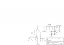
There is normally a high value resistor from the output side of the output capacitor to ground (470k-1M) to tie it to 0v if the input of the amp is DC coupled. (otherwise high voltage spike can get into the amp, and not mention give you a shock if you touch the output. (missing from lampizators schematic)
There is normally a high value resistor from the output side of the output capacitor to ground (470k-1M) to tie it to 0v if the input of the amp is DC coupled. (otherwise high voltage spike can get into the amp, and not mention give you a shock if you touch the output. (missing from lampizators schematic)
There is normally a high value resistor from the output side of the output capacitor to ground (470k-1M) to tie it to 0v if the input of the amp is DC coupled. (otherwise high voltage spike can get into the amp, and not mention give you a shock if you touch the output. (missing from lampizators schematic)
Thank you for pointing out, will insert one too, better play safe.
Regarding heater psu. Ive got some 7v transformers here that i dont need. After rectification they should give about 9,8V. I read that voltage drop for the LM317 is 1,7V, so this should play fine.
Wrong.
It's current output DAC.
Thanks for pointing that out. I adressed my mistake in post #11 but adressing it two times is better I suppose.
Regarding heater psu. Ive got some 7v transformers here that i dont need. After rectification they should give about 9,8V. I read that voltage drop for the LM317 is 1,7V, so this should play fine.
The voltage is never 1.4 times the input voltage after rectification because of losses (resistance) in the windings of the transformer. You also loose about 1 V in the rectifier. I would go for 10 V (or more) to be absolutely sure. It's easier to drop some voltage than to gain it...
The TDA1541A is a current out DAC.
It isn't that it is a dual triode, it is the specific circuit. The two triodes in your circuit could be single triodes, or triodes from different dual triodes or in the same dual triode.
That 75v is only true as long as the B+ is limited to 150, but many issues in the power supply could easily have it rise like the failure of a resistor in the ps or pass element if regulated. It is so close to 100v even voltage surge on line could make it higher without a failure. Unliky to go that high without failure with a 120v transformer though. With a 120v secondary transformer I would use a minimum 200v as the output capacitor, but you might consider 160v safe enough. Note that it is not just the capacitor you are trying to protect, it is the downstream gear.
The TDA1541A is a current out DAC.
It isn't that it is a dual triode, it is the specific circuit. The two triodes in your circuit could be single triodes, or triodes from different dual triodes or in the same dual triode.
That 75v is only true as long as the B+ is limited to 150, but many issues in the power supply could easily have it rise like the failure of a resistor in the ps or pass element if regulated. It is so close to 100v even voltage surge on line could make it higher without a failure. Unliky to go that high without failure with a 120v transformer though. With a 120v secondary transformer I would use a minimum 200v as the output capacitor, but you might consider 160v safe enough. Note that it is not just the capacitor you are trying to protect, it is the downstream gear.
I understand now what the problem is, yes. I think i will go on a higher voltage, because there are 2 different caps that i like very much. One is 100V and the other 800V, so i will go on the 800V and i should be safe.
Hi,
this seems the right corner on diyaudio for my questions.
I want to use a 6N2P tube for IV conversion of my I-out TDA1541A DAC. I will use a 90ohm wire wound resistor. I found an implementation by Lukasz Fikus here :
http://lampizator.eu/lampizator/references/SATCH/IMG_5501.jpg
He uses a 120V transformer (although the tube can go up to 250V ???) and also a 2uF output cap.
My 2 questions are : Is it somehow better to use a lower voltage on this tube or why is he using such a low input voltage ?
Second question : I read somewhere that you should use high quality output caps. But most of my MKP caps are 2.2uF and not 2uF. Should i use two 1uF and bridge them or can i use 2,2uF without any problems ?
I have some higher quality caps from mundorf and other brands that i could use, but they are all 2,2uF. The caps that i like most at the moment (at least for passive crossovers on speakers) are Jantzen Alumen Z caps. They sound very good in high and mid ranges on crossovers (not as harsh as many of the cheaper ones). Will there also be such a big improvement over cheap caps if i use them as output caps (on passive crossovers it is) ? And the Alumen caps are also only 100vdc. Will this matter in an IV stage ?
use much lower value of Riv because of the specified DC offset less than 25mV
Larger values of Riv will cause higher distortion...
And in that case Tube stage is not IV stage but the amplification stage.
Current injection at output of 2mA is welcome for the tda1541
Yo will have phase shift of 180deg on Riv BUT single tube stage (or any other type) will have also phase shift of 180deg. So Riv followed by 1 amplification stage will outputs in phase sygnal.
SRPP for my opinion is not good topology for the sound reproduction. Simple anode follower is much better. In the name of father son and holly spirit do not use SRPP 🙂
If You need lower output impedance put tube buffer after aplification stage,
With lower imperance buffer You can use some interstage transformer at the end.
path:
Current injection+Riv_anode follower no feedback bypassed RK_buffer_output C
happu buiding 🙂
You dont need any input C because after adjusting 2mA to Iout of the dac ypu will have 0mV offset...
Even with offset that will be stable offset so it can easely adjusted by making Rk a bigger value to match desired negative biasing for the tube...
...
With ECC83 You can use some rechargeable battery of 1.5V for kathode biasing still without local feedback. And You can parrallel sections for say total 5mA anode current so this will be trickle charging for AA battery.
Old school like Neuman did before 60-70 years with some riaa preamplifiers 🙂
Buffer could be DC coupled (without C) and with ECC88 for the aproximate 200ohms of output impedance.
This type of dac output stage deserves tube rectifier and old school power supply with minimum 2 inductors (chokes) 🙂
- Home
- Amplifiers
- Tubes / Valves
- Help on tube IV