Thanks for all the suggestions.
How low should i go and would other parts also change their values or is it only the IV R ?
use much lower value of Riv because of the specified DC offset less than 25mV
Larger values of Riv will cause higher distortion...
How low should i go and would other parts also change their values or is it only the IV R ?
Do you know where i can see this setup as schematic ? Im a tube beginner, was building class a until now 🙂Current injection+Riv_anode follower no feedback bypassed RK_buffer_output C
Last edited:
If you want to comply with the 25mv offset you'll need an I/V resistor of 12.5r so you will need the valve to be an amplifier with gain enough to provide the output signal level you need.
You can leave out the 2ma injection if you use an input coupling capacitor. (you can compare the sound with and without the current injection)
You can leave out the 2ma injection if you use an input coupling capacitor. (you can compare the sound with and without the current injection)
You can go low as to meet the datasheet less than 25mV offset. say 4.7 ohms to 10 ohms
Dac outputs 4mA p-p
with 6.8 ohm Riv it will be 0.004A x 6.8 ohm = 0.0272 V output at Riv
next stage for 1V p-p should have gain of 36.8 X (1V / 0.0272V)
.
with 4.7 ohm Riv it will be 0.004A x 4.7 ohm = 0.0188 V output at Riv
next stage for 1V p-p should have gain of 53.2 X
for these amplifications 6SN7 or ECC81 or tubes with similar mju factor will be good.
If You want higher output signal use tube set with more gain like ECC83
.
If You are already build something that working, with tubes You can built simple DAC output stage too?
.
I will try to draw schematic.
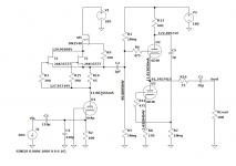
For current DAC I use this scheme, the first tube is I / V conversion with gain of 40, the next stage is white cathode folower.
The output voltage is around 6Vpp with an input current of +/- 1.2mA (PCM1702), for the TDA1541 it will be slightly higher, 18Vpp, which is quite enough to drive any amplifier.
An ordinary cathode folower can be used instead of a WCF.
The output voltage is around 6Vpp with an input current of +/- 1.2mA (PCM1702), for the TDA1541 it will be slightly higher, 18Vpp, which is quite enough to drive any amplifier.
An ordinary cathode folower can be used instead of a WCF.
Attachments
If You are already build something that working, with tubes You can built simple DAC output stage too?
.
I will try to draw schematic.
It would be very very nice if you could draw a schematics. Thank you very much.
I build a lot of output stages with opamps and 3 different with discrete parts (jfet). But this is the first time that i try to do one with tubes, never worked with them.
I first wanted to try the lukasz fikus iv stage, because i have some 6n2p tube here for 5 or 6 years now and could use them in this project, but if the alternatives are better, i will buy them. I also found a 120/140V transformer, but this would limit the gain very much, most tubes use a much higher b+.
For current DAC I use this scheme, the first tube is I / V conversion with gain of 40, the next stage is white cathode folower.
The output voltage is around 6Vpp with an input current of +/- 1.2mA (PCM1702), for the TDA1541 it will be slightly higher, 18Vpp, which is quite enough to drive any amplifier.
An ordinary cathode folower can be used instead of a WCF.
Thank you. Ok, now i understand a bit how a tube can be used for i/v. Still need to simulate this one, so i learn a bit more. Ty
You can go low as to meet the datasheet less than 25mV offset. say 4.7 ohms to 10 ohms
Dac outputs 4mA p-p
with 6.8 ohm Riv it will be 0.004A x 6.8 ohm = 0.0272 V output at Riv
next stage for 1V p-p should have gain of 36.8 X (1V / 0.0272V)
.
with 4.7 ohm Riv it will be 0.004A x 4.7 ohm = 0.0188 V output at Riv
next stage for 1V p-p should have gain of 53.2 X
for these amplifications 6SN7 or ECC81 or tubes with similar mju factor will be good.
If You want higher output signal use tube set with more gain like ECC83
.
If You are already build something that working, with tubes You can built simple DAC output stage too?
.
I will try to draw schematic.
I've read many times about the distortion caused by too high an I/V resistor but never seen this quantified.
What sort of distortion?
How much?
Where is it worst, low frequencies or high and at low levels or high?
Where are the figures for the benefits of injecting 2ma?
Using a high gain tube amplifier will introduce additional distortion which might exceed the distortion from a high I/V resistor (eg 100R)
It would be very very nice if you could draw a schematics. Thank you very much.
I build a lot of output stages with opamps and 3 different with discrete parts (jfet). But this is the first time that i try to do one with tubes, never worked with them.
I first wanted to try the lukasz fikus iv stage, because i have some 6n2p tube here for 5 or 6 years now and could use them in this project, but if the alternatives are better, i will buy them. I also found a 120/140V transformer, but this would limit the gain very much, most tubes use a much higher b+.
A 140v rms secondary will give you about 240v dc with full wave rectification - enough for most preamp tubes.
Attachments
Most schematics that i have seen with tubes use two independent psus for two heaters. Is there any kind of advantage over using one and then parallel supply the two heaters ?
If i have two 350mA heater and my psu can go as high as 1A, can i use one psu and parallel them or is there a reason, that i dont see to not do that?
If i have two 350mA heater and my psu can go as high as 1A, can i use one psu and parallel them or is there a reason, that i dont see to not do that?
Its two tubes, two heaters. Each tube 6.3v, 350mA. Parallel with only 1 psu or not ?Most schematics that i have seen with tubes use two independent psus for two heaters. Is there any kind of advantage over using one and then parallel supply the two heaters ?
If i have two 350mA heater and my psu can go as high as 1A, can i use one psu and parallel them or is there a reason, that i dont see to not do that?
I read somewhere (perhaps in this mega forum Building the ultimate NOS DAC using TDA1541A but I could not find the exact location) that this 25mV thing is not a strict rule. I made a quick test using 100 ohm I/V resistor, the TDA1541A was driven by an USB-I2S converter, and measured with a FFT analyzer software. The 2nd and 3rd order distortion did not grow significantly. Sorry I don't have screenshots. If you use too low I/V resistor, the following stage must have high gain, that implies distortion and noise.I've read many times about the distortion caused by too high an I/V resistor but never seen this quantified.
What sort of distortion?
How much?
Where is it worst, low frequencies or high and at low levels or high?
Where are the figures for the benefits of injecting 2ma?
Using a high gain tube amplifier will introduce additional distortion which might exceed the distortion from a high I/V resistor (eg 100R)
A good solution is to use a common grid stage (as proposed by grunf) where the cathode presents a low impedance load to the DAC chip.
Or simply use a transformer 😉
.
Thorsten's tube Stage for TDA1541A
Winner (all else lost)
-
I have the 160H Tango plate chokes, G.Pimm v5 CCS, and some nice custom OPT 2:1.
-
And best depends on too many things, the trick is to find a tube that biases okay close to 0V grid, use 22-47R grid leak (I/V) and make use of 1541A DC offset (-2mADC), one that is low noise, long life and linear. 6072A, 6922, and as triode connected pentodes: E180F, E280F and D3a
-
Try it (first and last).
Last edited:
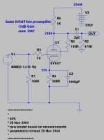
This is a output stage for TDA1541A with ECC83 as amplifying tube and 5687 tube as buffer.
Amplifing tube as most sensitive part is set to most linear region. And high anode voltage because tube is voltage device not current... Operating points are chosen not to exceed maximal values given by datas. It is posibile to use battery in kathode bias for ECC83 tube.
Citcuit showing extremly low distortion, and have excellent phase at the ends of the bandwidth. I will check sleave rate and other parameters.
For the buffer I will check some mere configurations and afordable tubes
I avoided ECC88 tube as low voltage (max 130V anode voltage) and open anode internala construction.
.
This circuit does not have additional filtering or compensation circuits. That could be optionally added.
.
I will post Zanden style passive notch filter network later for optional?
Attachments
I read somewhere (perhaps in this mega forum Building the ultimate NOS DAC using TDA1541A but I could not find the exact location) that this 25mV thing is not a strict rule. I made a quick test using 100 ohm I/V resistor, the TDA1541A was driven by an USB-I2S converter, and measured with a FFT analyzer software. The 2nd and 3rd order distortion did not grow significantly. Sorry I don't have screenshots. If you use too low I/V resistor, the following stage must have high gain, that implies distortion and noise.
A good solution is to use a common grid stage (as proposed by grunf) where the cathode presents a low impedance load to the DAC chip.
Or simply use a transformer 😉
Its a balancing act between I/V resistor and noise and distortion in the high gain preamplifier so I'll stick to Sowter's transformers, which are perfect for dual differential 1541s and Ian's I2S to PCM board.
I tried 100ohm and 20ohm, because i had wire wound resistors of this values and i have to say, that besides the gain difference i cant hear a really noticeable difference in quality. I prefer none of the both, so i will stick to 20ohm, so i get closer to the 25ma recommended.
Guys, which kind of resistors do you use for such an i/v stage (besides the r iv) ? Is there any advice what is best ? i have standard resistors at 2W and some mox ones, but they are only 1/4 watt. Is there any benefit in using mox and is 1/4 watt enough for the tubes (not in the psu, at the tubes themselves) ?
Guys, which kind of resistors do you use for such an i/v stage (besides the r iv) ? Is there any advice what is best ? i have standard resistors at 2W and some mox ones, but they are only 1/4 watt. Is there any benefit in using mox and is 1/4 watt enough for the tubes (not in the psu, at the tubes themselves) ?
Nobody can help with the resistors ? Do i need 2W ones for the 6n2p at 150v or can i safely use 1/4 Watts for the 200ohm resistors at the tubes ? Like in Fikus‘ iv for example.
You can safely use 1/4 (= 0.25) Watt resistors. The current through the resistor will be under 1.5 mA, so the voltage drop over the 200 Ohm resistors will be under 0.3 V. So P = I x V = 0.0015 x 0.3 = 0.00045 Watt.
For me I wouldn't like using a 6N2P (or 12AX7/ECC83) with only 0.3 V as bias voltage because at these low bias voltages some grid current will flow. But I have no idea if the amount of grid current is large enough and/or changes enough with signal to have any effect on the sound/performance.
For me I wouldn't like using a 6N2P (or 12AX7/ECC83) with only 0.3 V as bias voltage because at these low bias voltages some grid current will flow. But I have no idea if the amount of grid current is large enough and/or changes enough with signal to have any effect on the sound/performance.
Which resistor? The I/V ones can be anything you've have,
There's no harm in using 1 or 2w for the other low power types.
There's no harm in using 1 or 2w for the other low power types.
- Home
- Amplifiers
- Tubes / Valves
- Help on tube IV