Nice work Vunce and your initial impressions are very encouraging indeed. Can I ask if you are going to package it in a nice enclosure to finish it off?
Can't wait to start on mine, boards arriving today and parts I have ordered will be here on Monday.
It sounds like you should be proud of your work Borko.
Looking forward to your listening impressions with that more than difficult load for this type and size of amp Vunce.
Can't wait to start on mine, boards arriving today and parts I have ordered will be here on Monday.
It sounds like you should be proud of your work Borko.
Looking forward to your listening impressions with that more than difficult load for this type and size of amp Vunce.
Thanks Gary 😉
Yes, I will finish it off. The amp is currently standing upright. Picture lying it down, the makerbeam rails that are attached to both sides of the heat sinks are going to be the attachment points for the top and bottom aluminum panels. The rear panel, approximately 11” wide, will attach to the meaty sections of heatsinks with fins exposed. The front panel will span the entire width approximately 17”. So ultimately, it will look like a conventional type chassis with the front panel clean, heat sink fins visible from the top, sides, bottom and rear.
That’s the plan......but you know how the best laid plans go 😀
Happy Building!!
Cheers!
@ Vunce,
Regarding your post #237, looks like a softstart circuit in the background, right side. What about the background left side, some kind of filter?
Regarding your post #237, looks like a softstart circuit in the background, right side. What about the background left side, some kind of filter?
I use this board as a test bed, it has a Fo-Felix AC filter and an old DIYA store softstart circuit onboard.
GB: Round #6; Fo-Felix AC Filter
GB: Round #6; Fo-Felix AC Filter
Hi,
I wonder using split power supply to avoid output coupling capacitors. This thing also same as your SE-CFA gain stage project.
Is there available that version?
Regards,
I wonder using split power supply to avoid output coupling capacitors. This thing also same as your SE-CFA gain stage project.
Is there available that version?
Regards,
Hi,
I wonder using split power supply to avoid output coupling capacitors. This thing also same as your SE-CFA gain stage project.
Is there available that version?
Regards,
Didn't try that with the amplifier, don't have a time but I guess it could be done...
Hi,
I wonder using split power supply to avoid output coupling capacitors. This thing also same as your SE-CFA gain stage project.
Is there available that version?
Regards,
The front panel knobs will have to be avoided in that case. You can't change feedback etc., on the fly as it would affect offset.
The front panel knobs will have to be avoided in that case. You can't change feedback etc., on the fly as it would affect offset.
Yes, with controls, servo is needed.
Yes everything works in theory 😊
There could be lot permutations with this kind of topology but it must be optimised in real life. I don't think cfp in aleph ccs is worth extra parts. Another thing, without cap in feedback network, you wold probably need some kind of servo.
There could be lot permutations with this kind of topology but it must be optimised in real life. I don't think cfp in aleph ccs is worth extra parts. Another thing, without cap in feedback network, you wold probably need some kind of servo.
Thank you for your feedback, Bogdan. I just have a thing for bipolar cfp, like some others do for mosfets.
About the feedback cap and bias: that is a dilemma, with a low value jfet source resistor one needs a pretty big capacitor, and I would rather not have that. We will see what happens with bias in a real circuit.
What simulation model do you use for the 2sk932? I made one up using the datasheet, but is probably not very good. And I am afraid it was not working at all in the spice file that I posted above, so here it comes again:
Attachments
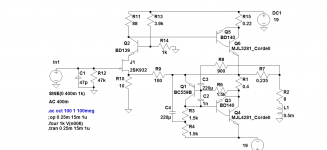
This is an update of the circuit, now it has about 9dB less feedback, I think it sounds better and transient behaviour is lot better, no overshoot on a square wave... The corrections are in red on the schematic, Rs added and C10 and R14 have different values (other end of the R14 is now conected to the output node, not gnd like before).
Cheers, Borko.
Cheers, Borko.
Attachments
Bogdan,
That is a very well designed amp, congratulations!
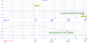
Can you show us the loop gain and stability parameters?
I'm very curious and I'm very conscious you have very carefully chosen very good components; BD140/2SC5200 is optimal for stability, and very nice compensation, well done.
That is a very well designed amp, congratulations!
Can you show us the loop gain and stability parameters?
I'm very curious and I'm very conscious you have very carefully chosen very good components; BD140/2SC5200 is optimal for stability, and very nice compensation, well done.
Would 2SK170 or BF 862 be good alternatives for the specified input JFET, viz., 2SK932? Thanks.
Yes.Would 2SK170 or BF 862 be good alternatives for the specified input JFET, viz., 2SK932? Thanks.
Loop gain:Bogdan,
That is a very well designed amp, congratulations!
Can you show us the loop gain and stability parameters?
I'm very curious and I'm very conscious you have very carefully chosen very good components; BD140/2SC5200 is optimal for stability, and very nice compensation, well done.
Attachments
Thanks for the update Borko.
Shall we consider that the HP is directly connected to OUT and GND connectors?
(Assuming one uses Prasi's pcb.)
Shall we consider that the HP is directly connected to OUT and GND connectors?
(Assuming one uses Prasi's pcb.)
Thanks for the update Borko.
Shall we consider that the HP is directly connected to OUT and GND connectors?
(Assuming one uses Prasi's pcb.)
What is HP?
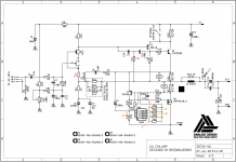
Prasi pcb needs litle bit of revision, for updated version, but I can't do it, never worked in eagle, I've done my pcb in Altium..
Last edited:
Sorry for the confusion, sometimes mixing up several languages :-/
Was speaking about the speakers, shall one simply connect them using the OUT and GND connectors? Or is it better to connect the speaker-ground to some kind of ground star?
Was speaking about the speakers, shall one simply connect them using the OUT and GND connectors? Or is it better to connect the speaker-ground to some kind of ground star?
Sorry for the confusion, sometimes mixing up several languages :-/
Was speaking about the speakers, shall one simply connect them using the OUT and GND connectors? Or is it better to connect the speaker-ground to some kind of ground star?
Speaker gnd shoud be on the main pcb, not star ground of the amplifier power supply.
- Home
- Amplifiers
- Solid State
- Single Ended CFA