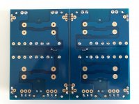
I'm working on my J as well, a couple questions on the power supply board:
1. If I tie GND 2.2/3.2 together with multiple jumpers, then I can use the euro blocks for any grounds, right? In other words, I don't need the faston tabs there if I use bare wire to the blocks for ground?
2. What do I need to do with ST_IN2 and ST_IN3? Looks like rhing jumped those together.
3. C17/C18 and R11/R12 should be left open, along with the optional_R 1-6, correct? I see references to the snubbers, and I'm assuming those are R11/12 and C17/18 and leave open for the J PS.
Thanks as always and happy labor day!
I'm working on my J as well, a couple questions on the power supply board:
1. If I tie GND 2.2/3.2 together with multiple jumpers, then I can use the euro blocks for any grounds, right? In other words, I don't need the faston tabs there if I use bare wire to the blocks for ground?
That is correct. Placing the jumpers between both sides creates a single PSU ground.
2. What do I need to do with ST_IN2 and ST_IN3? Looks like rhing jumped those together.
I placed additional jumpers between those locations for the power supply ground.

3. C17/C18 and R11/R12 should be left open, along with the optional_R 1-6, correct? I see references to the snubbers, and I'm assuming those are R11/12 and C17/18 and leave open for the J PS.
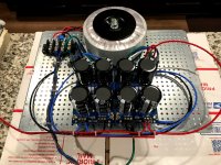
You are correct. 6L6 recommends removing the snubber components: C17, C18, R11 and R12. I built an almost identical power supply for my Pass DIY Sony VFET amplifier almost two years ago, and I did not install the snubber components (see photo below). I wasn't thinking when I built this latest one for the Aleph J.

By the way, this Sony VFET amp is a very special amp. I am very hopeful that the Aleph J will give me as much music listening pleasure when I complete it.
thank you Rhing...I did as you suggested; another question if I may:
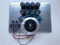
How do you mount that transformer to the bottom plate? I am using Antek transformer, do you just drill out a bigger hole in the base plate and use the supplied bolt?
How do you mount that transformer to the bottom plate? I am using Antek transformer, do you just drill out a bigger hole in the base plate and use the supplied bolt?
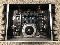
Exactly. Using a 4U Deluxe chassis myself, the AnTek transformer sits over the edge of the perforated bottom panel to provide as much room as possible for the monolithic bridge rectifiers and power supply board. I located the centerline row of holes (side-to-side) and counted 5 rows inboard from the overhang edge. Sorry, I can’t remember the drill bit size I used. I think I used a 5/16 in. drill bit.


Hope this helps.


Hope this helps.
Hello. I am currently waiting on three aleph-J amplifiers together with three universal power supplies my goal with these is to make two three channel amplifiers for my marchand active crossover that I have built which will drive DIy Zaph audio three way speakers also which i am in the process of building. My question is about the power supply. Can I separate one of the boards so that I can drive 3 pairs of rails to power each amplifier channel using 2 300Va toroids in each amplifier one with dual 18V secondaries and one with single 18V secondary. Hope I have been clear enough.
Each channel needs a positive rail and a negative rail. I don't see how you can do that with a single board and single secondary.
Jezza56 - Someone with more experience and certainly more brains than I should comment further.
You're saying 2, 3-channel amplifiers. So, I am assuming that by "amplifier" you mean that you'd like 2 chassis containing 3 single channels of amplification each. Each chassis would have it's own mains connected power supply, along with 3 sets of speaker binding posts, and perhaps 3 sets of inputs; one for each speaker.
If you've already determined heatsinking and general configuration; then you perhaps don't need even 3 separate PSUs, just two. You could consider a suitably rated single transformer (perhaps 500-600VA) along with perhaps additional / beefier components for higher current (if necessary depending on how you'd configure) and run 3 amplifier boards from each PSU. Each PSU having V+ and V- rails. No need to split or go to other extraordinary measures. It may even reduce potential for ground loops etc. It's generally accepted to run two channels from one "PSU", why not more?
Once again, PLEASE ensure someone that knows what the heck they're really doing confirms or says this idea is trash before considering. It's only an idea.
Head - Yes, you are spot on.  As you suggest, merely increase the transformer VA and slightly bigger filter capacitors.
 As you suggest, merely increase the transformer VA and slightly bigger filter capacitors.
My question is about the power supply. Can I separate one of the boards so that I can drive 3 pairs of rails to power each amplifier channel using 2 300Va toroids in each amplifier one with dual 18V secondaries and one with single 18V secondary. Hope I have been clear enough.
I agree with the suggestions above. I built 6 channel Aleph J in one huge chassis for active setup. I'm afraid if I understand your question correctly, but yes, you can power 3 boards with one supply (which consists of one positive and one negative). That's what I did. If you have 3 chassis and 2 supplies, grounding scheme might be a little tricky, though.
What you want to be careful is a voltage sag and wattage of CRC resistors because more current through CRC resistor than normal. Also transformer itself has its own impedance, so I also would suggest larger than normal 18V or 20V transformer for 3 boards.
Last edited:
rhing I believe you want q1a and q1b to be thermally joined. A bit of heatsink compound and a zip tie or heat shrink tubing to hold them together. Not sure how easy that will be with them soldered to the board
I built 6 channel Aleph J in one huge chassis for active setup.
I'd love to see some pictures of that amplifier!
6 channel aleph-J
I guess I sort of complicated my initial post. But yes I want to build a 6 channel aleph-J amplifier 3 stereo inputs and 6 pairs of speaker outputs. Thanks to everyone inputs I will go with the 600VA transformer in each chassis supplying 1 power supply in each chassis and increase cap bank to 180000 uf. So will it be better to go with 20V instead of 18V sec? One more question does anyone know how We can purchase Toroidy transformers or a suitable alternative in Australia. Thsnk you all for your inputs it is greatly appreciated.
I guess I sort of complicated my initial post. But yes I want to build a 6 channel aleph-J amplifier 3 stereo inputs and 6 pairs of speaker outputs. Thanks to everyone inputs I will go with the 600VA transformer in each chassis supplying 1 power supply in each chassis and increase cap bank to 180000 uf. So will it be better to go with 20V instead of 18V sec? One more question does anyone know how We can purchase Toroidy transformers or a suitable alternative in Australia. Thsnk you all for your inputs it is greatly appreciated.
What is preventing you from building three separate stereo amps?
The power dissipation from six channels would be massive. Better to just build three power supplies and have six heat sinks to dissipate the heat.
The power dissipation from six channels would be massive. Better to just build three power supplies and have six heat sinks to dissipate the heat.
This was what I was intending to do before I got suggestions from other diyers. I would like to build two 3 channel chassis as real estate in my listening area is quite limited. I have Turntable, Phono stage peamp, rotel amplifier marchand active crossover and if you add 3 x 5U power amplifiers it would get quite crowded. I intend to design and build my own chassis which will allow for 3 mono boards each with their own heatsink. I am thinking also that it may be cheaper to build two large 3 channel than 3 smaller two channel. This is just supposition at the moment as I haven't had a chance to crunch numbers. But I definitely will look at your idea also.
Jezza
Jezza
@Jezza56, 18V vs 20V is something hard to answer. I would suspect that you'll probably see around 21V rail with 18V/600VA/6A, which is fine, but a little lower side. Normally, AJ rail is around 22V with suggested parts here, I guess.
I used 20v on my AJ and unloaded came in a tad over 29v. Once loaded it was slightly over 25v
Since the Aleph J is a relatively high bias current design, several factors affect the final rail voltage somewhat more than is seen in other amps.
Power transformer secondary voltage sag. May be mitigated by using higher voltage secondaries and higher VA rating, or dual-mono PSU.
Bridge rectifier forward voltage drop. May be mitigated by using lower Vf bridge rectifiers, including 'ideal' LT4320 synchronous rectification. Almost anything is better than the usual GBPC blocks.
Resistive loss in the CRC (or CRCRC) filter network. Sort of a given: V = Iq * 0.117 Ohms for typical CRC. Different for CRCRC depending on choices for R. Also different if CLC is used.
As one may infer, the PSU is the main area where the builder can make choices that affect the sound quality of their amp. The channel boards work so well as a standard build, that there's no reason to change anything.
Hello together,
I think I´m winning the idiot fo the month award:
After building the Aleph J everything went fine. It only had 2 mV DC on its outputs and was dead quiet.
After listening to a few records, I connected my laptop. With this in line I had a an audible hum. After trying this and that I taped the laptops net-ground and connected it to 250V.
It immediately banged and now theres a big hum on the right channel of the Aleph J.
It´s there if a source is connected and if not. The level of the hum can´t be regulated with a volume pot. If I connect it with music the hum is there, but music will be audible.
I can´t see damaged any parts.
What could have happened?
Last edited:
check DC offset, check Iq, check current through input LTP (measure at CCS on top of it)
it took me several re-reads to grasp that you isolated with tape grounding tabs on mains plug of laptop ("taped")
can't see how that could any harm ........ it must be something else coincidental
it took me several re-reads to grasp that you isolated with tape grounding tabs on mains plug of laptop ("taped")
can't see how that could any harm ........ it must be something else coincidental
- Home
- Amplifiers
- Pass Labs
- Aleph J illustrated build guide