Well, actually adding a high capacitor at the regulator's output is not the same thing as local decoupling.It's a fndamental choice actually.When you charge the output with a big capacitor you reduce all the regulator bandwidth to nothing...and rely entirely on the output capacitor's esr as an energy storage for the electronic circuits downstream.I see tons of "high end"very complex regulators followed by a 10 000 uf capacitors...That capacitor is actually using the regulator only for charging them between the fast transients...so you can always use a very fast regulator with a high capacitor at the output with good results at reducing 50hz hum...
A Simple Method to Determine ESR Requirements for Stable Regulators | Power Electronics
A Simple Method to Determine ESR Requirements for Stable Regulators | Power Electronics
Well, actually adding a high capacitor at the regulator's output is not the same thing as local decoupling.It's a fndamental choice actually
Sorry if that wasn't clear. I put the big caps before the regulator. 10 uF on the output is fine. Datasheets say you have to have something there.
I also addressed local decoupling.
sory if it felt like attacking you....it's an audiophile reflex to replace any capacitor with a 1000x higher value 🙂
Another reflex is very low ESR cap.
It is a bad idea for the cap at the output of these regulators.
It is a bad idea for the cap at the output of these regulators.
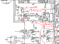
to be honest i was never interested in these theories, being actually on the "practical side|" most of my life until i met this wonderful Nakamichi BX300 cassette deck which was a revelation to me.Apart from its noise supressing techniqe it has a virtual ground generator with no cap at its otput relying entirey on op-amps bandwidth , cmrr and psrr.
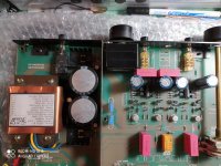
At the same time its +-12v regulator has nothing but a 10 000uf capacitor at the output.And it's a NAK...so maybe it's not that bad to rely on capacitor's abilities more than the reglator's bandwidth...
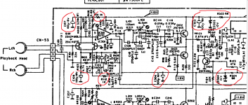
Some time ago i was convinced that they must have a such complex regulator regulator to make it faster...until someone prompted me to the 1k-100uf rc constant in red circle...
I'd really like to get a really professional comment on that nakamichi regulator phylosophy as it's found in al their high end cassette deck, including the Dragon and ZXL-1000, but i'm afraid i will never get one so i have to trust my guts when i make assesements on what , where and when i should use some particular topology. As for that nak regulator i believe that that topology is done like this in order to survive a catastrophic dead short at its output .
At the same time its +-12v regulator has nothing but a 10 000uf capacitor at the output.And it's a NAK...so maybe it's not that bad to rely on capacitor's abilities more than the reglator's bandwidth...
Some time ago i was convinced that they must have a such complex regulator regulator to make it faster...until someone prompted me to the 1k-100uf rc constant in red circle...
I'd really like to get a really professional comment on that nakamichi regulator phylosophy as it's found in al their high end cassette deck, including the Dragon and ZXL-1000, but i'm afraid i will never get one so i have to trust my guts when i make assesements on what , where and when i should use some particular topology. As for that nak regulator i believe that that topology is done like this in order to survive a catastrophic dead short at its output .
Attachments
Last edited:
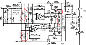
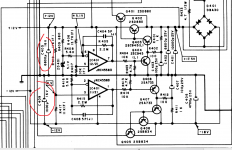
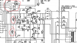
Yet...if it's a nakamichi zxl-1000 it doesn't mean it's shy at using a simple zener regulator after that fancy regulator.
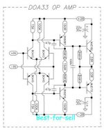
And another zener plus decoupling for its most sensitive part , the tape-head preamp and here's the most expensive tapehead playback circuit in history...
And another zener plus decoupling for its most sensitive part , the tape-head preamp and here's the most expensive tapehead playback circuit in history...
Attachments
Last edited:
Thanks. However i have been suggested to place other 470uF per rail close to the preamp circuit when there is a little distance between the regulators and the circuits. I would put the regulators directly in the circuit ... i remember always the DNA series from Mc Cormack ...Sorry if that wasn't clear. I put the big caps before the regulator. 10 uF on the output is fine ...
McCormack Audio POWER DRIVE DNA - 0.5 amp, McCormack Audio Audiophile POWER DRIVE DNA - 2 Amp, McCormack Audio POWER DRIVE DNA - 1 Amp, McCormack Audio "The McCormack Micro amp
.... DNA series of amplifiers are distinguished by their unique distributed node amplifier design for which they are named. This concept entails distributing the energy storage of the main power supply over a number of small capacitors. In a DNA amplifier, each output device has a separate power supply capacitor located immediately adjacent to the transistor. This distributes the current demands,establishes an individual power reservior for each output transistor, and enables higher transient current flow to each device by minimizing impedance in the circuit path.
i find this reasonable 🙄
I'm talking about line level, not a power amplifier. 470 uF is appropriate for local bypass of a power amp board. No point for line level circuitry.
sory if it felt like attacking you...
I don't mind clarifying points. I do not feel attacked.
To be specific, the datasheet says the capacitor is needed for stability. It also states that if there's another capacitor within a certain distance (30 cm? I'd have to look it up) then there's no need for the 10 uF output capacitor.
.it's an audiophile reflex to replace any capacitor with a 1000x higher value 🙂
I'm an engineer and an audiophile. I'm well aware of the pitfalls of carelessly increasing capacitor values, and I'm also aware of methods to mitigate the effects of a bigger capacitor in a circuit. I learned that partly by trial and error. I shoot for a dominant pole of 1.6 or 3.2 Hz if practical.
Generally, more is better. Both caps and transformers, etc. This is based on actual listening experience that exceeds engineering calculations. Try it and see!
Dreamth, thanks for the Nak repro schematic. Good circuit for mid fi, but I made more sophisticated repo circuits for my master recorder electronics. More expensive too!
Dreamth, thanks for the Nak repro schematic. Good circuit for mid fi, but I made more sophisticated repo circuits for my master recorder electronics. More expensive too!
Nak zxl-1000 is mid fi due to cassette tape medium, not because of the electronics quality...
Reanalyzed the Nak voltage regulators with a fresh eye...these are the slowest regulators ever relying entirely on capacitors for energy drain .There's no need for fast tranzients regulation which aren't fast anyway due to the nature of tape head transducers.Power transistors have 3...5 mhz transition frequency and i think i finally understood their "philosophy" which is actually that they only needed to filter a lot of cassette player circuits.They were aimed entirely at reducing mains hum and providing enough current for the circuits.For a DAC supply regulation the cheap LM7812 is faster and better...
Reanalyzed the Nak voltage regulators with a fresh eye...these are the slowest regulators ever relying entirely on capacitors for energy drain .There's no need for fast tranzients regulation which aren't fast anyway due to the nature of tape head transducers.Power transistors have 3...5 mhz transition frequency and i think i finally understood their "philosophy" which is actually that they only needed to filter a lot of cassette player circuits.They were aimed entirely at reducing mains hum and providing enough current for the circuits.For a DAC supply regulation the cheap LM7812 is faster and better...
Last edited:
Actually checking the hi-fi stadards i just realized that most good cassette decks exceed even the hi-fi norms!Dreamth, thanks for the Nak repro schematic. Good circuit for mid fi, but I made more sophisticated repo circuits for my master recorder electronics. More expensive too!
http://www.hifimuseum.de/45-500-die-englische-version.html
Generally, more is better. Both caps and transformers, etc. This is based on actual listening experience that exceeds engineering calculations. Try it and see!
Already tried it and you're right. That is for power amplifiers anyway.
I beefed up the power supply of an old Pioneer receiver with fresh smoothing caps. I replaced the dried up antique capacitors with an array of smaller capacitors. Then I added local bypass right by the output transistors; electrolytic and big film capacitors were tacked to the bottom of the board right on the power transistor leads. These changes made a very audible difference. Bass was better, mids were clearer, highs were way cleaner. This is on a 30 year old unit pulled out of the trash.
My buddy replaced the transformer in his power amp with a bigger one he sourced from the manufacturer. That single change kicked the bass up a notch for sure. No other changes were made.
This is why classic amplifiers like Krell sound so good. The circuitry and construction of these units can only be described as antiquated. But the power supply is overkill; big beef with all the fat.
I was only using the power amp of the Pioneer. The preamp section worked but it was profoundly terrible. No amount of turd polishing could come close to redeeming it.
I needed a power amp for my system at the time. I bypassed the power amp section and added a couple of RCA jacks to the back. I used it daily for about three years. My power amp now, which is a Selfless clone, is much cleaner sounding but doesn't come close to the power of the Pioneer. It was supposed to be a prototype but it's been my daily amplifier for about two years. Of course I'm building a much larger version of it.
I needed a power amp for my system at the time. I bypassed the power amp section and added a couple of RCA jacks to the back. I used it daily for about three years. My power amp now, which is a Selfless clone, is much cleaner sounding but doesn't come close to the power of the Pioneer. It was supposed to be a prototype but it's been my daily amplifier for about two years. Of course I'm building a much larger version of it.
Thanks ! and now that i think more preamps are usually working in class A that means constant current draw from the circuit.I'm talking about line level, not a power amplifier ....
A steady state. Big caps are needed, i guess, mostly in AB designs where the current draw from the circuit varies with the signal. And caps take care of the current demand peaks ? current is not constant
I will put back in the originals soon .... these are 1000uF 😱
However i count 10 bjts /channel ... and it is just a line stage providing about 10dB of gain plus current
In the more recent designs they have reduce the number of active parts to 8 per channel and i guess with improvements in the performance
In the assumption that newer is better of course
Attachments
Sorry you mean that an oversized power supply is the reason of great sound ? even if the circuit design has limits ? well this is very interesting... This is why classic amplifiers like Krell sound so good. The circuitry .... antiquated. But the power supply is overkill ...
round and round always going back to power supply quality ... actually i have seen preamps where the amplification circuit is very tiny compared to the power supply. In some cases at least part of the power supply is even in a separated chassis.
I have seen a very interesting video where a manufacturer tells about a comparison of two version of the same exact preamp, one with the mains transformer in the same chassis and the other with the transformer taken out .... the latter sounded better
I do not have reason to doubt his words.
I am thinking to take out the mains transformer and add maybe a mains filter before it. Other mods could destroy the very delicate unit.
Not exactly. But the power supply can affect performance.Sorry you mean that an oversized power supply is the reason of great sound ? even if the circuit design has limits ?
Measure the power supply voltage while driving a load. How much it droops is an indicator or how well it's performing. 10% droop at full power is considered good. I've measured 40% droop when driving speakers with music.
Power supply is just one factor, but it's an important one.
ref. post 337
Thanks again for the very helpful advice. I was thinking to place an analog voltmeter just across the ps caps terminals and see for oscillations In the best case it should stay still even when the amp delivers good power
I have read somewhere that mains transformer and ps caps are correlated. It is possible to use a higher VA transformer and using smaller caps or a smaller VA transformer and using bigger caps.
If i understand well one secret of very good sounding units stay more in the mains transformer able to provide a good steady current to the diodes.
Krell amps in particular have a tradition of using huge mains transformers
The big good ones are very expensive.
Many commercial amps have very weak transformers. Some manufacturers used to propose upgrades in the power supply like Odyssey Audio with their caps upgrade and Mission Electronics with the PSX for their integrated.
Thanks a lot again.
Moreover ... someone advised me that a bc413 cannot drive properly a MJE 172 (this would lead to higher distortion)
I wonder if this can be confirmed.
Another question would be can the 2n5210/2n5087 pair replace the bc413/bc415 pair as input stage ?
What is the main benefit of using a input stage of 4 bjts instead of the simpler classic diffential pair ?
I see 3 stages ... is it the very minimal solution ? better PSRR maybe ? less distortion ?
Last edited:
I was thinking to place an analog voltmeter just across the ps caps terminals and see for oscillations
Exactly. But be careful. The voltages can be dangerous and a short can be catastrophic, as well as dangerous.
In the best case it should stay still even when the amp delivers good power
It won't unless it's a class A amplifier.
I have read somewhere that mains transformer and ps caps are correlated. It is possible to use a higher VA transformer and using smaller caps or a smaller VA transformer and using bigger caps.
It's about ripple current. Best to go big both ways if possible. But there are some serious limitations.
Droopy power supplies in commercial amplifiers aren't just about saving money on power supplies. It allows for a smaller heatsink and helps keep the transistors closer to their SOA. It sounds cheesy, but... it's pretty much the industry standard.
Of course, some amplifiers don't compromise. They go big, they cost a lot of money, they stand the test of time because people are still using them, fixing them, talking about them. You know which ones I'm talking about.
Many commercial amps have very weak transformers. Some manufacturers used to propose upgrades in the power supply like Odyssey Audio with their caps upgrade and Mission Electronics with the PSX for their integrated
Yeah but if you put a bigger transformer in, then the diodes see more average and peak current, the capacitors see more charging current, the amplifier will probably produce more heat, etc. Everyone's done it but it can be like putting a bigger engine in a car - it'll run better if you drive it reasonably but stuff is still going to be more likely to break.
Exactly. But be careful. The voltages can be dangerous and a short can be catastrophic, as well as dangerous.
The best way to monitor something like PS "droop" and such is to use clip leads, or clips on the probes.
Ya gotta have the right "tools" beforehand.
- Home
- Member Areas
- The Lounge
- Overengineering in audio equipment