I have been able to simulate the air velocity on the mouth of my transmission line, the only last small concern I had about my build.
So this update comes right on time, before I glue the cabinets.
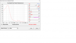
Here it is at 39V/250W. Thank you David!
I hear 17m/s is the limit before we can hear port chuffing In the case of my transmission line where airflow is a lot more laminar, I'd expect this is less critical than on bass reflex port. Anybody has a view on this?
BUILD3_20200827_AirVelocity.png
So this update comes right on time, before I glue the cabinets.
Here it is at 39V/250W. Thank you David!
I hear 17m/s is the limit before we can hear port chuffing In the case of my transmission line where airflow is a lot more laminar, I'd expect this is less critical than on bass reflex port. Anybody has a view on this?
BUILD3_20200827_AirVelocity.png
Attachments
Last edited:
Hi GM,
When the System Model acoustic circuit block diagram was first added to the Loudspeaker Wizard the diagram was displayed by default when the Wizard was opened. This was later changed in the update released 29/06/20 so that the standard schematic diagram again became the default. Are you seeing something different to this, perhaps? Schematic 1 has never been the default.
Kind regards,
David
Greets!
No, it displays 'schematic' and I guess this is the correction I thought applied to my 'complaint' and don't recall it being an issue for me, so guess I didn't use it during this time frame.
OK, after actually paying attention to what's currently happening, 'return', 'default' are technically poor descriptions.
Historically when I'm in the LW it opens to 'schematic', then open 'displacement'/whatever, then want to move back to 'schematic', the expanded display listed 'schematic' at the top, but with an earlier revision it changed to 'schematic 1' in the top spot when [re]opened, so got to scroll up to 'schematic', which gets tedious when doing a bunch of quickie comparisons.
BTW, what is 'schematic 1' for? No joy searching the HELP file.
TIA,
GM
Hi GM,
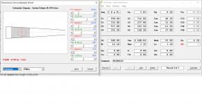
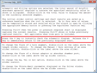
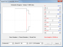
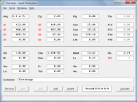
Whether Schematic or Schematic 1 appears at the top depends on the type of system, and on the number of items in the 'Outputs' dropdown list. Attachment 1 shows an example where Schematic 1 appears at the top and Attachment 2 shows an example where Schematic appears at the top. Either way, you are making life difficult for yourself by clicking and scrolling to access the schematic 🙂. Simply press the V (for View) key to instantly check the schematic diagram, and release the V key to immediately return to the previously displayed screen. Attachment 3 refers.
Note that it is possible to move from say Displacement (if highlighted) to Power by simply pressing the P key twice ( the first time switches from displacement to phase, the second time from phase to power), it is not necessary to open the dropdown list and scroll upwards. Use other first letters as appropriate for other outputs (I for Impedance, etc).
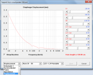
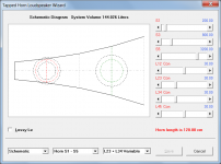
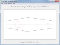
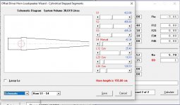
Schematic 1 shows an elevation view of the specified chamber and port arrangement in a tapped horn or other system having an offset driver. The elevation view is included because it is sometimes difficult to envisage the configuration of chambers and ports by looking at the plan view dashed circles in the standard schematic diagram. Attachments 4 and 5 refer.
I try to make using Hornresp as easy as possible - there are short cuts everywhere... 🙂.
Kind regards,
David
Historically when I'm in the LW it opens to 'schematic', then open 'displacement'/whatever, then want to move back to 'schematic', the expanded display listed 'schematic' at the top, but with an earlier revision it changed to 'schematic 1' in the top spot when [re]opened, so got to scroll up to 'schematic', which gets tedious when doing a bunch of quickie comparisons.
Whether Schematic or Schematic 1 appears at the top depends on the type of system, and on the number of items in the 'Outputs' dropdown list. Attachment 1 shows an example where Schematic 1 appears at the top and Attachment 2 shows an example where Schematic appears at the top. Either way, you are making life difficult for yourself by clicking and scrolling to access the schematic 🙂. Simply press the V (for View) key to instantly check the schematic diagram, and release the V key to immediately return to the previously displayed screen. Attachment 3 refers.
Note that it is possible to move from say Displacement (if highlighted) to Power by simply pressing the P key twice ( the first time switches from displacement to phase, the second time from phase to power), it is not necessary to open the dropdown list and scroll upwards. Use other first letters as appropriate for other outputs (I for Impedance, etc).
BTW, what is 'schematic 1' for?
Schematic 1 shows an elevation view of the specified chamber and port arrangement in a tapped horn or other system having an offset driver. The elevation view is included because it is sometimes difficult to envisage the configuration of chambers and ports by looking at the plan view dashed circles in the standard schematic diagram. Attachments 4 and 5 refer.
I try to make using Hornresp as easy as possible - there are short cuts everywhere... 🙂.
Kind regards,
David
Attachments
Hi David,
I was looking at this : Active Compliance Management (ACM) — VUE Audiotechnik . I know...akabak ^^ But if ME tool allowed Nd to be vented in addition to ME1, with a bit of mind twisting, it could be another case for wich hornresp should make life easier 😀
😉
Damien
I was looking at this : Active Compliance Management (ACM) — VUE Audiotechnik . I know...akabak ^^ But if ME tool allowed Nd to be vented in addition to ME1, with a bit of mind twisting, it could be another case for wich hornresp should make life easier 😀
😉
Damien
Member
Joined 2009
Paid Member
I recently downloaded the latest version.
It worked for awhile, then Windows Defender removed it, where it went I know not but it's gone. So I had to download it again and reinstall it - which required my daughter to enter her password because it's her laptop (I use only Mac). Well, it worked for a couple of days and now the Windows Defender took it away again - it's gone. As my daughter is canoeing through the wilderness I can't download it and re-install for several days. Never had any trouble with the previous version. Is anybody else having trouble like this ?
It worked for awhile, then Windows Defender removed it, where it went I know not but it's gone. So I had to download it again and reinstall it - which required my daughter to enter her password because it's her laptop (I use only Mac). Well, it worked for a couple of days and now the Windows Defender took it away again - it's gone. As my daughter is canoeing through the wilderness I can't download it and re-install for several days. Never had any trouble with the previous version. Is anybody else having trouble like this ?
Whether Schematic or Schematic 1 appears at the top depends on the type of system, and on the number of items in the 'Outputs' dropdown list.
Either way, you are making life difficult for yourself by clicking and scrolling to access the schematic 🙂. Simply press the V (for View) key to instantly check the schematic diagram, and release the V key to immediately return to the previously displayed screen. Attachment 3 refers.
Note that it is possible to move from say Displacement (if highlighted) to Power by simply pressing the P key twice ( the first time switches from displacement to phase, the second time from phase to power), it is not necessary to open the dropdown list and scroll upwards. Use other first letters as appropriate for other outputs (I for Impedance, etc).
Schematic 1 shows an elevation view of the specified chamber and port arrangement in a tapped horn or other system having an offset driver.
I try to make using Hornresp as easy as possible - there are short cuts everywhere... 🙂.
Greets!
Thanks! I wondered if it was simply due to increasing the list options.
Hmm, OK, Thanks! Where are these 'shortcuts everywhere' in HELP? I vaguely remember having various humongous 'cheat sheets' full of cryptic abbr., symbols to navigate the various main frames we had over the decades at the plant and when communicating/interacting between plants, Corporate, etc., as well as the various programs pertinent to our jobs, but don't recall any basic/generic set like you describe, though did notice awhile back that I could scroll through these, but mostly aggravating due to arthritis no longer allowing me any 'finesse', only 'ham-fisted' control.
Ah! Guess I'm fortunate in that I don't [yet] have any problem visualizing them in 3D.
Regardless, quite a program that apparently now has more features that were 'never going to happen' than it started with!
 😀
😀GM
Getting closer to be able to design what I am looking for. 🙂
It can already be done, if absorbent filling material is not required. If absorbent filling material is required, simply remove the step. The results will be effectively the same with or without stepped segments.
Attachments
Where are these 'shortcuts everywhere' in HELP?
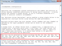
Some are documented in the Help file (for example, in Edit mode, double-clicking on the text box containing the number of drivers to immediately open the Loudspeaker Configuration form, rather than being required to use the Tools menu) and some are inherent in the Microsoft Visual Basic functionality itself (for example, using the first letter of an item name in a dropdown list box to select the item option, rather than having to scroll through the list).
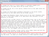
Another random example - I have noticed in Hornresp videos posted online that most users seem to adjust the Loudspeaker Wizard slider controls manually, even when the changes to be made are quite large. This can take considerable time. It can be faster to just directly enter a value "somewhere in the ballpark", and then only do the fine tuning optimisation using the slider. Also, it is possible to rapidly scroll through slider values by pressing and holding the Home or End key while the slider has the focus, which is another way of saving time when setting values.
Attachments
Thanks for the answer David! Appreciated.It can already be done, if absorbent filling material is not required. If absorbent filling material is required, simply remove the step. The results will be effectively the same with or without stepped segments.
As i recall it I couldn´t come this far last time I used the software (April??). Or maybe it was when i moved into the fill mode I got stuck. The filling makes such a big difference in this design so its really needed to be designed. What I think you say is make the best possible design with the stepped approach, store it, remove the step, design the filling levels in the now "no step design" and put equal amount of filling in the stepped cabinet when building it?
Or wait for a future feature that allows me to design this type of stepped design also in the filling part. 🙂
Hi Sharky,
The procedure you describe should get you close enough for all practical purposes.
Additional area sliders would be required in the Loudspeaker Wizard to specify the steps, which would complicate things greatly. I can't see it happening.
Stay safe,
David
make the best possible design with the stepped approach, store it, remove the step, design the filling levels in the now "no step design" and put equal amount of filling in the stepped cabinet when building it
The procedure you describe should get you close enough for all practical purposes.
Or wait for a future feature that allows me to design this type of stepped design also in the filling part. 🙂
Additional area sliders would be required in the Loudspeaker Wizard to specify the steps, which would complicate things greatly. I can't see it happening.
Stay safe,
David
Thanks
"Additional area sliders would be required in the Loudspeaker Wizard to specify the steps, which would complicate things greatly. I can't see it happening."
Maybe something else will due, such as a % field for defining the size of the start of the next section versus the size set by the slider for end of the previous section. Just thinking 🙂
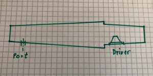
So the inner starting point is S1.
S2 is where the driver is positioned and is the end of the first section.
S2 is also the start size of the second section.
S3 is the end of the second section
S3 is also the size of the start of the third section
S4 is where the port/vent is postioned
S4 is also the start size of the fourth section
S5 is the end size of the fourth section
S3 is where in this design a %-field would be benficial. Although it might complicate the actual computations for filling, which i have no idea if so.
"Additional area sliders would be required in the Loudspeaker Wizard to specify the steps, which would complicate things greatly. I can't see it happening."
Maybe something else will due, such as a % field for defining the size of the start of the next section versus the size set by the slider for end of the previous section. Just thinking 🙂
So the inner starting point is S1.
S2 is where the driver is positioned and is the end of the first section.
S2 is also the start size of the second section.
S3 is the end of the second section
S3 is also the size of the start of the third section
S4 is where the port/vent is postioned
S4 is also the start size of the fourth section
S5 is the end size of the fourth section
S3 is where in this design a %-field would be benficial. Although it might complicate the actual computations for filling, which i have no idea if so.
I even tried a simpler version of my above design, without the port. A very simple design. Failed already on S1-S2. 🙂
As S1 is smaller than S2 the L12 vaule disapeared and Bes showed up instead (a Bessel horn). If I enter the L12 length here in "Bes" the rest of the line input cells is greyed out and nothing more can be done. I know that i am doing something wrong here (I see myself as a veeeeery logical guy, but this application bugs my brain, sorry), but I have a really hard time figuring out what. It should be extremely simple as it to me seem very straight forward.
S1 = 423 cm2, S2 = 466,6, L12 = 25,4 cm, S3 = 483,9, L23 = 10,1, S3:2 405,24 (after the step), S4 = 42,34, L34 = 120,1. Driver SBA SB17NRX2 positioned as S2.
Attachments
Last edited:
such as a % field for defining the size of the start of the next section versus the size set by the slider for end of the previous section.
I suspect it would be easier to just include the additional area sliders 🙂.
As S1 is smaller than S2 the L12 vaule disapeared and Bes showed up instead
S1 = 423 cm2, S2 = 466,6, L12 = 25,4 cm, S3 = 483,9, L23 = 10,1, S3:2 405,24 (after the step), S4 = 42,34, L34 = 120,1. Driver SBA SB17NRX2 positioned as S2.
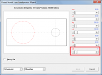
With the L12 (Bes) input box highlighted, enter C25,4 to specify a conical first segment of length 25,4 cm.
If you then double-click the Con label it will change to Exp, double-click again and it will change from Exp to Par, double-click again and it will change from Par back to Con.
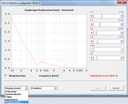
If I understand your design specification correctly, your input window needs to look like the attached.
Attachments
I suspect it would be easier to just include the additional area sliders 🙂.
I think so too.
They are already there in the input menu. 👍😉
If I understand your design specification correctly, your input window needs to look like the attached.
Correctly understood. After a few restarts I actually got the figures in. I still don’t know why sometimes the rest of the input menu is greyed out. And I still don’t understand why I sometimes can have different values in the S-position (in this case S3) as the section end point and then next starting point but sometimes it’s not possible. I don’t really understand why the length fields (Con, Bes etc) sometimes is impossible to get a value in when trying (with an error message that the value is zero, which it is as the field change the value to zero whatever value that is put in there)...
The first "section" actually section 1 and 2, where the driver is positioned is represented as cylyndrical instead of cylindrical as they are, but the next section is actually presented as cylindrical for some reason (tried to read why in the manual, but didnt find it).
I did notice that your ”Ang” is 2,0xPi and mine is 0,5.
The next design is to change the open end to a closed end with a port/vent.
Attachments
Last edited:
- Home
- Loudspeakers
- Subwoofers
- Hornresp