Can anyone explain to me what O/P means?
Sorry it was standard shorthand for output in my studies, likewise I/P.
There are loads of abbreviations about which I do not have a clue on this forum, maybe it is just the change with time in electronics culture.
Then the gauge pressure goes negative ... i trust you. Never seen measurements to be honest.
Actually it goes negative with respect to atmospheric pressure. Technically, it's still positive.
thanks This is an important confirmation I also read that is the Vas that contributes more to the sound. So if the Vas is single ended the sound could be more musical maybe ?
The Vas stage typically drives the output stage via its collector. A collector is basically a current source. The input impedance of a typical output stage (Darlington etc) is a very nonlinear impedance; the impedance falls with rising base current. The transfer curve is not a straight line at all but part of a parabola. This is a simplified explanation too.
The best workaround is Doug Self's addition of an emitter follower after the Vbe stage. This flattens out the transfer curve considerably and greatly mitigates the distortion.
well the Pass Aleph series and the diy BOZ are indeed single ended. I think he felt the need to give a theorical basis to his design choices ?
Single ended amplifiers still push the cone in and out. That's what i meant with my comment.
I see the schematic ... they are single ended no feedback
I understand that his last commercial units are different but i do not know for sure.
I know for sure. I've seen them in the store. They are not minimalist designs that a beginner can build at home.
Mr. Self has brought some innovative designs to market in his day. Look at his "Stasis" technology that he licensed to Nakamichi. It's not conventional at all; it uses two global feedback loops, like two amplifiers connected in series. He uses clever workarounds to make it all work in a consumer product.

I even do not know if stability can be checked with sim
SPICE simulates stability.
I do not know if an audio design can be scaled up or down.
To a degree. You can certainly scale power amps up within reason.
Taking for instance a very good design working for a preamp stage increasing the V supply and the power of the devices maybe i could end with an equally nice power amp
Probably not.
thank you very much indeed for the very kind and valuable advice.
You're welcome. I hope it helps.
If you try a diode, I recommend doing it in a signal cct rather than on the O/P of a power amp.
Hi ! actually that is what i was thinking to get current flow only in the push direction 😱 it does not work i guess 🙁
Hi ! yes of course ... but i thought it were not possible to go below the atmospheric pressure. I was wrong .... the sound wave create also a series of pression and depressionActually it goes negative with respect to atmospheric pressure. Technically, it's still positive.
Issue closed thanks a lot
does it have something to do with the Szikai pair ? because i have seen Doug Self's pages mentioning it I have seen this pair in many preamp schematics on service manuals one being the old Onkyo P303 and another one the Kenwood 700c They were TOTL preamps in their timeThe Vas stage typically drives the output stage via its collector. A collector is basically a current source. The input impedance of a typical output stage (Darlington etc) is a very nonlinear impedance; the impedance falls with rising base current. The transfer curve is not a straight line at all but part of a parabola. This is a simplified explanation too.
The best workaround is Doug Self's addition of an emitter follower after the Vbe stage. This flattens out the transfer curve considerably and greatly mitigates the distortion.
It should have been popular in the late '70s
Usually these preamps had a buffer output stage of the Sziklai kind
And there are many people who speak highly of their sound.
and this closes the issue. I thought that a SE amp made the woofer behaved differently I think i have not understood the Mr Pass pages thenSingle ended amplifiers still push the cone in and out. That's what i meant with my comment.
I know for sure. I've seen them in the store. They are not minimalist designs that a beginner can build at home.

i see him mentioned very often The Naka Stasis series is quite famousMr. Self has brought some innovative designs to market in his day. Look at his "Stasis" technology that he licensed to Nakamichi. It's not conventional at all; it uses two global feedback loops, like two amplifiers connected in series. He uses clever workarounds to make it all work in a consumer product.
a really great tool this Spice I have to find a manual for beginnersSPICE simulates stability.
Thanks a lot again I asked this because gain is never little ... actually there is often too much gain So i was thinking that always keeping an eye on stability the same schematic could be used for power amps with different power just increasing number of output devices and V supplyTo a degree. You can certainly scale power amps up within reason.
It helps a lot indeed. I think that i should start with simulating some basic discrete opamp circuits and checking their distortion and stability. This would be a very good start. Thanks again.You're welcome. I hope it helps.
Last edited:
Let me word it this way: sound waves are ac - pulsating around the athmospheric DC-bias of average barometric pressure.
Hi ! actually that is what i was thinking to get current flow only in the push direction 😱 it does not work i guess 🙁
Well far less risky, (and I think it will sound terrible), but you still do not know the absolute phase of the signal, which itself will be dependant on what happened in the recording, mixing, and mastering processes.
does it have something to do with the Szikai pair ? because i have seen Doug Self's pages mentioning it I have seen this pair in many preamp schematics on service manuals one being the old Onkyo P303 and another one the Kenwood 700c They were TOTL preamps in their time
Why yes it does use a Sziklai class AB output stage. Unlike the circuits you've probably seen, it is configured for gain (I think the gain is 3 if I remember correctly). It is a stand alone buffer. It is not inside the feedback loop of the amplifier stage that drives it. It's all DC coupled. The topology is similar to a global feedback amplifier with Szilkai output stage but there's two feedback loops, not one.Go to hifiengine.com, register, and look at the Nakamichi TA-2A schematic. That's the stasis power amplifier.
Thanks a lot again I asked this because gain is never little ... actually there is often too much gain
Gain structure is up to the designer. (That's you.) Optimizing gain structure makes a system nicer.
I think that i should start with simulating some basic discrete opamp circuits and checking their distortion and stability.
I think that's an excellent idea. I was going to recommend building a kit you like, but go with what works for you. 🙂

Let me word it this way: sound waves are ac - pulsating around the athmospheric DC-bias of average barometric pressure.
Thanks. I understand better now ... i thought that the actual pressure generated by a sound wave were staying always above the barometric pressure or at this pressure but never negative. I was clearly thinking wrong. I have misunderstood the points in Mr Pass's paper.
Well far less risky, (and I think it will sound terrible), but you still do not know the absolute phase of the signal, which itself will be dependant on what happened in the recording, mixing, and mastering processes.
Perfect ! it was another silly idea of mine ... 😱 thanks for injecting sanity in my mind 🙂
Thanks a lot I know that site very well. I will study the schematic you mention. Do you think that the design could be scaled down to serve as a high performance line stage ? maybe i have found what i am looking forWhy yes it does use a Sziklai class AB output stage. Unlike the circuits you've probably seen, it is configured for gain (I think the gain is 3 if I remember correctly). It is a stand alone buffer. It is not inside the feedback loop of the amplifier stage that drives it. It's all DC coupled. The topology is similar to a global feedback amplifier with Szilkai output stage but there's two feedback loops, not one. Go to hifiengine.com, register, and look at the Nakamichi TA-2A schematic.
That's the stasis power amplifier.
i am all ears ... requirements single supply 😱 few parts, V gain of 2-3 times, good driving ability to be usable with any power amp aroundGain structure is up to the designer. (That's you.) Optimizing gain structure makes a system nicer. I think that's an excellent idea. I was going to recommend building a kit you like, but go with what works for you. 🙂
I like the BOZ but in my version (pot at the input) i understand the Zout is around 1kohm ? a little too high ? and also the stage gain is a little too high
For the gain i know that i could change some resistors and get a lower gain but the little high Zout issue persists.
Thanks a lot again.
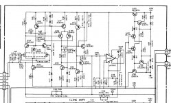
An op-amp...Hi and good morning. Before answering i would like to propose two schematics intended for the same purpose (i.e. line stage).
Same purpose quite different design approach ... which would be your pick ? 🙄
At the time when they launched these schematics there was no fet input op-amp with such dynamics and low noise as that NAk ca-50 circuit.It might still be better than most op-amps on the market if not all of them.
Could you please send me the ca-50II service manual on gopofirst@gmail.com? My country was banned 2...3 years ago by hifiengine for download or accessing their database and all the others ask for money.
Last edited:
Out of those two, I'd pick "Fig 10" but I'd build it with triodes 🙂Hi and good morning. Before answering i would like to propose two schematics intended for the same purpose (i.e. line stage).
Same purpose quite different design approach ... which would be your pick ? 🙄
An op-amp...
Could you please send me the ca-50II service manual on gopofirst@gmail.com? My country was banned 2...3 years ago by hifiengine for download or accessing their database and all the others ask for money.
check email 🙂have you tried a VPN maybe ? hifiengine is a huge source of service manuals
I used to buy many before discovering it
have a nice day 😀
Out of those two, I'd pick "Fig 10"
why not go with an hybrid solution ? a tube and a fet buffer for instance ?but I'd build it with triodes 🙂
i understand fets have a very high Zin very convenient with tubes and their high Zout
Also coupling caps can be small value
One night i could not sleep ... i have this nightmare of a single tube (i love 12bh7 do not know why) followed by a ss buffer as a line stage
Last edited:
No reason you couldn't go hybrid I guess... Tube voltage gain, MOSFET current buffer. I would use triodes because they are cheaper than heatsinks and they are more linear than MOSFETs. I also have a thing for depletion mode parts because the can be "cathode biased" 🙂
But as a source follower, it doesn't seem to matter much -- I'm listening to a hybrid SE MOSFET amp right now that is set up as a source follower.
But as a source follower, it doesn't seem to matter much -- I'm listening to a hybrid SE MOSFET amp right now that is set up as a source follower.
Last edited:
Thank you! I'm not really a computer geek...
Having a second thought on that nakamichi...i think there;s no solid state replacement for what it does ...It's supply rails are probably +-20...22v to be able to accept the phono preamp output with no significant overload .Kenwood, Pioneer, Akai had such circuits working up to +_43v supply rails .Either way you still need soft clipping circuits to limit phono input max input overload cause you can't go with +-25v pk to pk signals into any power amplifier. Mpsa 18 circuit has a secret in its sleeve, mpsa18 , besides being a very fast transistor has the most pronounced quasi saturation behavior and it might an anti saturation circuit by itself .
Having a second thought on that nakamichi...i think there;s no solid state replacement for what it does ...It's supply rails are probably +-20...22v to be able to accept the phono preamp output with no significant overload .Kenwood, Pioneer, Akai had such circuits working up to +_43v supply rails .Either way you still need soft clipping circuits to limit phono input max input overload cause you can't go with +-25v pk to pk signals into any power amplifier. Mpsa 18 circuit has a secret in its sleeve, mpsa18 , besides being a very fast transistor has the most pronounced quasi saturation behavior and it might an anti saturation circuit by itself .
A tube doesn't need a fet buffer, is way more linear than a fet , very high input impedance anyway .It might need a silicon bufer if it needs to feed a lower impedance than usual down the line, but most valves will handle silicon line inputs when wired as a unity gain cathode follower.I tried E282F, D3A, 6N6P in the past and i could drive 600 ohms headphones , not just line inputs...ECC83(12ax7) 6n1p , 6n2p, 12at7 , 6sn7, 6n7, 6n8 will do fine with line input.

- Home
- Member Areas
- The Lounge
- Overengineering in audio equipment