I get very high start currents; the SMPSs short circuit protection kicks in.
I can start the amplifier by connecting stage by stage.
Any ideas?
I'm also a little puzzled about C2 to C7, why are they needed?
I get a flat response without them...
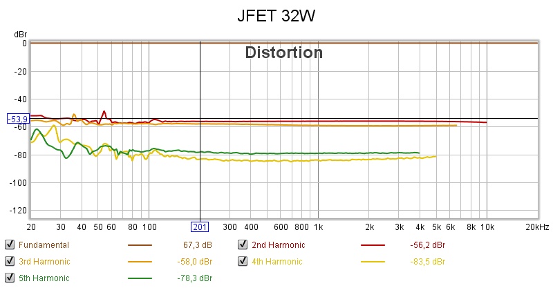
Anyway, the JFET SLAPS outperforms the previous variants of SLAPS for bass.
The load is a little bit high for the pre-amplifier though.
I can start the amplifier by connecting stage by stage.
Any ideas?
I'm also a little puzzled about C2 to C7, why are they needed?
I get a flat response without them...
As C2 to C7 charges up you get a very large power surge through the JFETs since they are depletion mode and act as an near short circuit with Vgs=0.
C2 to C7 is to shunt away the source feedback (degeneration) to get as much AC gain as possible. You probably don´t need them, but I would guess output impedance goes up without them (less feed forward error corretion due to less AC gain).
Can you measure distortion with and without them?
As C2 to C7 charges up you get a very large power surge through the JFETs since they are depletion mode and act as an near short circuit with Vgs=0.
Yes, I got that. But it'll be messy to connect the legs one by one in the finished amplifier.
It there anything to be done with the gate voltage in order to delay this?
C2 to C7 is to shunt away the source feedback (degeneration) to get as much AC gain as possible. You probably don´t need them, but I would guess output impedance goes up without them (less feed forward error corretion due to less AC gain).
Can you measure distortion with and without them?
Will do.
It there anything to be done with the gate voltage in order to delay this?
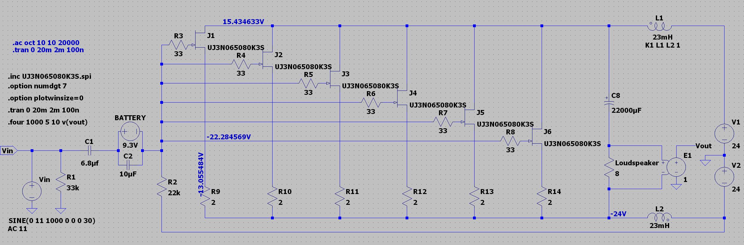
You could bias the gates negative with a small 9 volt battery, remove the C2 to C7 and lower the values of the source resistors to the right value needed for good current sharing and the correct amount of current through each JFET.

Something like this.
Have you measured the Vgs of the JFETs when they are up and running?
Will do.
10 dB more distortion with the capacitor.
For a single leg I get without/with capacitor:
2nd: -57/-47 dB
3rd: -73/-60 dB
4th: Below noise level/-76 dB
You could bias the gates negative with a small 9 volt battery, remove the C2 to C7 and lower the values of the source resistors to the right value needed for good current sharing and the correct amount of current through each JFET.
View attachment 870658
Something like this.
Have you measured the Vgs of the JFETs when they are up and running?
Thanks, I will try that.
Vgs is around -8.5 V.
In the topic of "10 W class A" there was a circuit for smooth charging of capacitors through a 10 ohm resistor in series with SMPS.
At the end of the charge, the relay shorted the resistor.
At the end of the charge, the relay shorted the resistor.
In the topic of "10 W class A" there was a circuit for smooth charging of capacitors through a 10 ohm resistor in series with SMPS.
At the end of the charge, the relay shorted the resistor.
Yeah, that's a good idea. Just a Nano with a relay board.
And it doesn't interfere with the signal path.
Last edited:
I put a 12 ohm resistor in series with the source resistors and short circuited them one by one after having switched on the SMPSs.
And it worked, so I guess relays could be a solution.
I 'll test the battery solution later.
Regarding the capacitors in parallel with the source resistors your explanation is spot on, Circlomanen.
At an input voltage that should output 8 W over a 7.5 ohm resistor,
I get without them 8.04 Vrms unloaded and 5.82 loaded (DF 2.82).
With the capacitors I get 8.24 and 7.79 respectively (DF 23.54).
So the distortion per se is not higher with the capacitors, but the output voltage is, thus leading to higher distortion levels.
This isn't true then:
Obviously, with no capacitors I get lower output power.The load is a little bit high for the pre-amplifier though.
I can only have four legs with the 4 ohm source resistors, the maximum current from the SMPSs is 6.5 A and each legs have a current of 1.4 A.
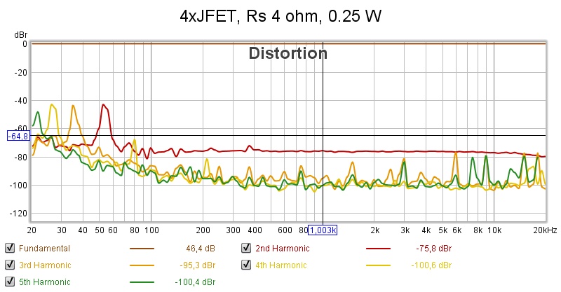
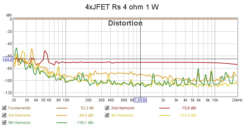
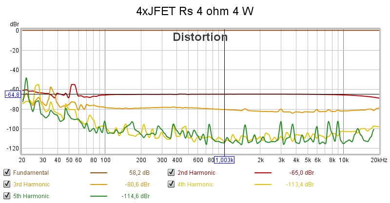
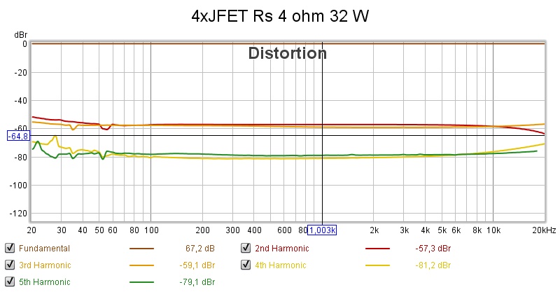
Some distortion measurement.
I have already established that the peaks under 100 Hz comes from the measuring equipment; computer DAC and ADC.
For the lower output powers the 2nd and 3rd looks really good.
4th and 5th is essential in the noise!
This amplifier is a rival for the 4 W amplifier, see SLAPS for SLAM!.
But more on that in that thread.
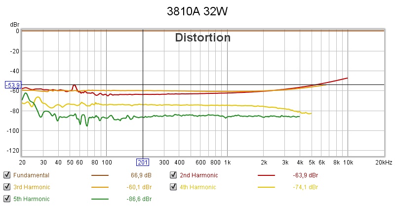
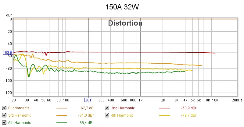
For 32 W the 3rd is in parity with the 2nd, 4th and 5th is still very low.
Is this then the SLAPS for bass amplifier?
I have already established that the peaks under 100 Hz comes from the measuring equipment; computer DAC and ADC.
An externally hosted image should be here but it was not working when we last tested it.
An externally hosted image should be here but it was not working when we last tested it.
An externally hosted image should be here but it was not working when we last tested it.
An externally hosted image should be here but it was not working when we last tested it.
For the lower output powers the 2nd and 3rd looks really good.
4th and 5th is essential in the noise!
This amplifier is a rival for the 4 W amplifier, see SLAPS for SLAM!.
But more on that in that thread.
For 32 W the 3rd is in parity with the 2nd, 4th and 5th is still very low.
Is this then the SLAPS for bass amplifier?
So these are the candidates:
Six IRFPS3810:
Six IRFP150:
Four stycken UJ3N065080K3S:
I don't quite like the high 3rd with IRFPS3810.
The teory says that a 2nd can mask a 3rd and as the amplifier shall drive bass element,
the 3rd might be audible at high SPL.
But then again, 32 W is 109 dB from one out of six bass elements in my setup.
Better 3rd with IRFP150 (and 4th and 5th.
But is the 2nd too high?
For the UJ3N065080K3S 2nd is lower but 3rd is perhaps too high
This amplifier is more complex though with high power resistors and slow start circuitry.
What do you think?
Six IRFPS3810:
An externally hosted image should be here but it was not working when we last tested it.
Six IRFP150:
An externally hosted image should be here but it was not working when we last tested it.
Four stycken UJ3N065080K3S:
An externally hosted image should be here but it was not working when we last tested it.
I don't quite like the high 3rd with IRFPS3810.
The teory says that a 2nd can mask a 3rd and as the amplifier shall drive bass element,
the 3rd might be audible at high SPL.
But then again, 32 W is 109 dB from one out of six bass elements in my setup.
Better 3rd with IRFP150 (and 4th and 5th.
But is the 2nd too high?
For the UJ3N065080K3S 2nd is lower but 3rd is perhaps too high
This amplifier is more complex though with high power resistors and slow start circuitry.
What do you think?
What do you think?
The higher levels of third harmonics from the IRFPS3810 and the JFET indicates that they have a more triode like character which the forward error correction can not correct. The second harmonic dominant behavior of those devices gets superimposed on the (floating) outputs which then shows up as a third harmonic. Low levels of expanding third harmonic makes the amp sound very powerful and dynamic. Compressive third harmonics tends to make everything sound very dull and lifeless.
I would guess that the only way to choose between these devices is by listening tests or by economic factors.
You could "slå två flugor med en smäll" when it comes to start up current rushing and filtering out the beat frequency from the SMPS power supplies.
A capacitance multiplier with a very large capacitor will have a very slow ramp up of voltage, which will slowly charge the C2 to C7 on turn on.
The capacitance multiplier will very effectively filter out any hum, noise, or fluctuating voltages.
Capacitance Multiplier Power Supply Filter
A capacitance multiplier with a very large capacitor will have a very slow ramp up of voltage, which will slowly charge the C2 to C7 on turn on.
The capacitance multiplier will very effectively filter out any hum, noise, or fluctuating voltages.
Capacitance Multiplier Power Supply Filter
All three have expanding (with increasing power) third harmonics but you think that the 150 will sound more dull?The higher levels of third harmonics from the IRFPS3810 and the JFET indicates that they have a more triode like character which the forward error correction can not correct. The second harmonic dominant behavior of those devices gets superimposed on the (floating) outputs which then shows up as a third harmonic. Low levels of expanding third harmonic makes the amp sound very powerful and dynamic. Compressive third harmonics tends to make everything sound very dull and lifeless.
Yes, I can build three pairs and test each solution with my woofers.I would guess that the only way to choose between these devices is by listening tests ....
And heat!... or by economic factors.

The beat frequency is barely audible with the PSU layout in the new boxes.You could "slå två flugor med en smäll" when it comes to start up current rushing and filtering out the beat frequency from the SMPS power supplies.
A capacitance multiplier with a very large capacitor will have a very slow ramp up of voltage, which will slowly charge the C2 to C7 on turn on.
The capacitance multiplier will very effectively filter out any hum, noise, or fluctuating voltages.
Capacitance Multiplier Power Supply Filter
Looks like a bulgy and a rather complex solution. I'd rather go for you first suggestion:
Is this the way to incorporate it?
An externally hosted image should be here but it was not working when we last tested it.
Last edited:
With six JFET legs and Rs 6 ohm, I get slightly better distortion levels but at much lower temperatures.
Is is then around 833 mA (5V/6ohm).
Is is then around 833 mA (5V/6ohm).
I would say - optimize on low 3,5,7th. One can ignore 2nd.
//
Yes, that's my thought as well.
But as the most work is to build the remaining boxes, with PSU, heat sinks and so on, I can easily change the MOSFET/JFET configuration at a later stage.
Here's a video on the FFT from 0.25 W (-28.4 dB) to 32 W (-7.4 db).
Last edited:
Start out with IRFP150. They should be quite similar to your SLAPS for SLAM amps in general character.
The JFET and IRFPS3810 are rather different breed of devices with more "personality".
The IRFP150 are much cheaper and do measure well. They should do a great job.
My guess is that the IRFPS3810 will have a more "forward" and energetic character and that the JFETs should be a bit mellow and smooth with less "in your face" kind of reproduction. To what extent this is audible and applicable for bass duty is an unknown.
Go for IRFP150! Cheap, simple and readily available in good quantities for close matching etc.
Start out with IRFP150. They should be quite similar to your SLAPS for SLAM amps in general character.
The JFET and IRFPS3810 are rather different breed of devices with more "personality".
The IRFP150 are much cheaper and do measure well. They should do a great job.
My guess is that the IRFPS3810 will have a more "forward" and energetic character and that the JFETs should be a bit mellow and smooth with less "in your face" kind of reproduction. To what extent this is audible and applicable for bass duty is an unknown.
Go for IRFP150! Cheap, simple and readily available in good quantities for close matching etc.
I will still build three pairs of amplifiers of each device.
Concerning the characteristics' similarities between IRFP044 (SLAPS for SLAM!) and IRFP150, I might find out that a SLAPS for SLAM! with the JFET measures quite well.
- Home
- Amplifiers
- Solid State
- SLAPS for bass.