you missed the Pioneer's output diamond buffer which has no global feedback but has a different approach for that matter to keep distortions low enough, not very low though...
Audio research has another diamond output too
Thanks for the schematics ... i need time to study them and try to understand something. But i am focusing the line stages that drive the power amp stages. That buffer i have attached is in the signal path ... if the sound is good that stage must also be good. Ok this is trivial but still ...
And it is good for one of the best integrated around it could be more than enough for my purpose as a beginner.
Thanks a lot again. Yes i guess it is an excellent point to start really.For the input buffer you might like to read this Tektronix manual who's bufferes were used by harman kardon in some designs i think .
https://www.davmar.org/TE/TekConcepts/TekVertAmpCircuits.pdf
But i need time ...
I didn't say it was impossible, but putting things into perspective consumer products are typically made to a price point and last a period of time that is acceptable to the consumer by in which time the product is obsolete or is uneconomical to repair, so the consumer simply buys a new one and we repeat the cycle.
In this case it maybe possible to make improvements, but you need to determine what are you trying to achieve by doing so, because it maybe the case that the improvements are so minor that its uneconomical.
I see. But people here do not look at economy when they build their units i guess. They use often the best part available and in some key points that can pay dividend like better inductors and caps in a speakers ... or more powerful mains transformers ... exotic diodes ... supply caps ... special resistors and so on.
The people who mod their units want to keep them most of the time.
Do you mean this thread - my dvd denon 2900 mod dazzz style 🙂
I wouldn't say talented although he may appear to be to those who lack sufficient electronics education. There are so many things wrong with the modifications that it is a tall ask to say they were improvements. Any improvements were simply a statement of replacing components therefore it must be better. I trust the guys at Denon...
Actually i was referring to Alex Peychev
Review: Denon 3910 APL solid state mod CD Player | Audiogon Discussion Forum
clearly he is not only pruning equipment ... i think it adds also other parts
But i like the idea of taking something basically good and elevate it to very good level.
And when this is the result of taking out things i am confused ... why they put them in ?
"There's no correlation between complexity and failure. Industrial, automotive and aerospace electronics are examples."
This feels instinctively wrong, an amp with 100 transistors has a greater chance that a transistor failure may occur.
And yes mchambin, I'd forgotten about Mean Time Between Failures.
This feels instinctively wrong, an amp with 100 transistors has a greater chance that a transistor failure may occur.
And yes mchambin, I'd forgotten about Mean Time Between Failures.
This kind of comments instantly shows thatn he has NO CLUE and to boot id full of it.“Scratchy, harsh, NOISEY, overly midrangey and they just severely lack detail. When comparing them to the NE5532, OPA2228 and OPA2604, the 4558 IMO is absolutely put to shame. Those chips have closer specs to a 12AX7 tube 😱 😕 and also sound/perform sooooo much better. When I play arpeggios through a circuit containing a 4558, there is such a lack of detail and raspiness that it would be embarrassing in a live performance.“
And he stinks of guitar shredder ... we all know how overblown they tend to be, by definition.
"Playing arpeggios" indeed! 🙄
That he got a couple followers (couple as in TWO) who are tuned to the same frequency and so praise his *opinion* adds nothing to his truthfulness.
Thousands of actual Engineers and Amp designers have done wonders with 4558, when it was the best commercial Audio Op Amp for a long time.
So good it has been slightly upgraded instead of fully replaced and is currently available and used (4560), go figure. 😎
Not many Op Amps can boast of that. 😎
EDIT: almost forgot:
Bedroom guitar hero detected 😎 😀 😛it would be embarrassing in a live performance.“
Last edited:
Thanks for the schematics ... i need time to study them and try to understand something.
Unfortunatelly our discussion digressed on the other topic(rotel...) so i can't really quote you unless out of context, but i think this is where i should answer you to another question about that silver bullet against common mode distortions while taking also the input noise of an op-amp into consideration.
Now, before anything else i want to point out that common mode distortions and intermodulation distortions aren't perceived as harmonic distortions, but as unwanted ugly noise. Up to a point harmonic distortions themselves are perceived also as noise, sometimes acceptable noise, but annoying over a period of time , over that point they are perceived as distortions that embelish the music depending on composition, and over that again they become ugly harsh noise.
I'm puting here a link provided by Salas in another topic to help you understand what i'm talking about:
https://www.eetimes.com/op-amps-in-...distortion-in-bipolar-and-jfet-input-op-amps/
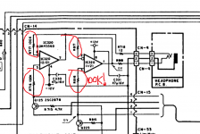
While other companies preffered for headphones amp to have a greater gain for a very well known headphones op-amp NJM4556, or like Yamaha using the inverted configuration, Nakamichi were again the real genious at improving a circuit as part of a whole, not independently of the other circuits of an audio equipment .
D.Self advised on using common mode cancelation resistor around 1 kohm, but nakamichi went for a monster Johnson noise resistor of 100kohm .It looked like they screwed it right? NO, and that is mainly because Johnson noise is perceived exactly as white noise which also have medical use .We like tape noise, we like vinyl groove noise....that's for a reason! It hides unwanted distortions and it's also relaxing the brain helping us hearing actually better and having a more pleasant listening than otherwise.
O2 headphones amp advised on using njm2068 in front two paralleled naked unity gain njm4556 for lower noise...Well...O2 forgot CMRR and PSRR with unity gain old op-amps adding a otherwise useless ultralow noise op-amp in front of it.Nakamichi simply evaluated the input current noise of NJM4556 (which by the way has a reasonably low input current bias )with that 100k resistors and actually got a pretty good noise figure because the 100k resistor not only worked out with the common mode distortions , but also lowered the overall RF pickup, power supply and intermodulation caused distortion noise too helped by the input capacitance of the op-amp.It was used in a cassette player, but a very low noise one and used with 16 bit cd's will also help with older ones dither, quite a lot.Well...I have a 2008 Norah Jones album that decided to use something like cassette tape recording on some songs and it sound really like s..t not even sound like a mild 19cm/s reel to reel noise, but very agressive dbx like breathing noise.I preffer a natural Johnson resistor noise instead.
Attachments
Last edited:
There's no correlation between complexity and failure. Industrial, automotive and aerospace electronics are examples.
This is so obviously wrong, I don' t understand one can think of such a thing.
Have a look at how a MTBF is calculated ?
"There's no correlation between complexity and failure. Industrial, automotive and aerospace electronics are examples."
This feels instinctively wrong, an amp with 100 transistors has a greater chance that a transistor failure may occur.
And yes mchambin, I'd forgotten about Mean Time Between Failures.
How can it be possibly wrong, the above statements couldn't be further from the truth, if it were the case everyday airplanes would be failing from the sky, highways and freeeways would be littered with 1000's of broken down cars and telecommunication systems would rendered useless.
MTBF for industrial products are typically in the 100K+ hours...do the maths.
Actually i was referring to Alex Peychev
Review: Denon 3910 APL solid state mod CD Player | Audiogon Discussion Forum
clearly he is not only pruning equipment ... i think it adds also other parts
But i like the idea of taking something basically good and elevate it to very good level.
And when this is the result of taking out things i am confused ... why they put them in ?
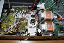
The Denon 3910 has very good audio specifications, not sure how you would improve on that beyond what the Denon engineers could do at the time.
Have you see pictures of the mods ? Can't see how its an improvement.
Attachments
Airplanes don't fall out of the sky because of redundancy, not complexity. The more parts there are, the more chance that one part will fail.
I have tubes in amplifiers that last for years, but the ENIAC? Not so much... "Several tubes burned out almost every day, leaving ENIAC nonfunctional about half the time. "
"If one of the tubes failed, the machine provided skewed results. With 17,468 tubes pulsing 100,000 times a second in the ENIAC, there were 1.8 billion chances of a tube failure every second. " IBM100 - IBM 603.
Redundancy (engineering - Wikipedia)
Triple modular redundancy - Wikipedia
Last edited:
According to this thread, at least this is my impression, the Honey Badger amplifier project is over-engineered. From the perspective of component count, it is definitely not a simple project, and considering how it works, it is even more not simple. Yet, so many users of this forum opted to build it, even though it costs somewhat more compared to many other projects.
My not so ripe experience designing an amplifier through a lot of simulations of different sub-circuit modifications, led me to conclude, that a good amplifier necessarily requires quite a count of components. This may not strictly hold for low power amplifiers, but high power amplifiers, where circuitry is more prone to the ill effects of parasitic latent components, have to use various measures to keep themselves behaving properly. It is a fact, low power circuitry, usually, has small parasitic latent components, but high power circuitry has more than enough of these hidden unwanted components. High power circuitry often suffer from unwanted ringing at the slightest excitation. For instance, through my long journey designing my amplifier, I was surprised to discover the drive feeding the driver stage's bases oscillates whenever it starts conducting current. The effect was not present at 1kHz, but showed it ugly head as the frequency increased. Through many many trials, I found using a signal diode with a small capacitor across connected between the driver stages' bases and VAS stopped the oscillation. Ripe members of these forums, strongly recommended me to remove the diode plus capacitor, as they suspected the parallel diode plus capacitor could couse unforseeable issues. Special thanks go to Mooly.
My experience thought me that unattractive complexity is a price that has to be frequently paid to get a better performance. One such complexity is a differential input with all it requires to behave according to expectations. A differential input is like an arbiter of the output which makes sure the output is always a fixed multiple of the input. This is achieved by having two signals opposing each other, with the error signal in the input driving the output. The error has to be very small compared with the actual input. All this requires components to be implemented and more components also mean more workarounds to tame their parasitic hidden components.
Last edited:
Safety and control circuits greatly reduce the chance of failure. Prudent circuit design, which dictates that products be goof proof in the hands of consumers, greatly reduces the chance of failure. Even adding a current limiting resistor in the input of a device (and maybe clamping diodes too) greatly reduces the chance of failure.
All these features increase parts count, yet reduce the chance of failure. My point is that you are making a blanket statement.
I learned my lesson a long time ago. Cutting corners results in drifting bias and offset, inconsistent performance, and catastrophic failures. I toasted exactly one woofer in my life and I'll never do it again.
I'll try to give an example of how increasing parts count can increase reliability. I'm setting up a control and protection circuit for a powerful 4 channel bi-amp. It consists of a timer and a transistor that resets the timer. (The transistor is controlled by the various detection circuits.) This is a small signal transistor, BC556. It resets the timer by shorting the capacitor in the timer circuit. Initially I had the transistor directly across the capacitor, a 4.7 uF electrolytic. The circuit worked fine and cycled hundreds of times without a hiccup. Then I started thinking about the surge current through the transistor, which is saturated when "on." I added a 100 ohm resistor in series with the capacitor, which limits surge current to around 100 mA max. The 100 ohm resistor doesn't affect the timer at all because it's in series with a 690K resistor.
It is my claim that the addition of that 100 ohm resistor will greatly reduce the chance of the transistor failing. The transistor has a far greater chance of failing than the resistor, when repeatedly subjected to current spikes greater than its maximum rating.
It is my claim that the addition of that 100 ohm resistor will greatly reduce the chance of the transistor failing. The transistor has a far greater chance of failing than the resistor, when repeatedly subjected to current spikes greater than its maximum rating.
You don't get one without the other. Redundancy, at least, doubles the parts count.Airplanes don't fall out of the sky because of redundancy, not complexity.
Engineering has nothing to do with ideologies.
System reliability is calculated using models and maths, mostly statistics and probabilities.
MTBF MTTR are the basics.
Redundancy, fewer parts are aspects of the problem. Isolated, out of context it is meaningless, what matters is the result of the overall system.
Some telephone exchanges were using duplicated computers, the required reliability in some cases was asking for triple computers.
These choices were not based on feelings or whatever to prove right or wrong but calculation to hopefully fullfill the reliability requirements.
The word engineering in the title of this thread could very well be nothing but a click bait.
I'm a test engineer and worked with high power lasers, medical equipment, high voltage smps, but i won't mix lasers reliability talk with audio equipment which is an entire different matter.But airplanes...they look like an entirely different ball game!
One very simple reliability test is to disconect one supply rail in dual supply amps and see what happens.Well..Lt Spice wont't tell you **** about the Bass speaker smoke...
Another simple test is to disconect the input to ground resistor or the rca input socket's ground or the feedback input in an op-amp or just run a dc sweep to the rails or short circuit the decoupling feedback capacitor and see what happens .Will the circuit survive? Will the dc output simply destroy everything downstream? These things happen often after a number of years of continuous play and the result is that we need to look for new transistors and speakers...
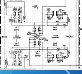
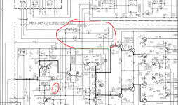
A few days ago looking into an active harman kardon equalizer i saw something strange.The turnover switch didn't shortcircuit one of the series capacitors as it's usually done, but simply switched between two different capacitors...That's's better from a distortion point of view due to lower capacitor losses , but what if the switch will fail to engage either of both sections? We'll have a partly disfunctional circuit until the switch is cleaned or replaced.At least all the competitors will have one eq turnover section working with a faulty switch.At least Harman Kardon left the 6x gain basic negative feedback out of the switches path so that if the tone eq /tone defeat switch fails the circuit will still be functional.
Now here comes the strange part: kenwood did the right thing with the tone eq, but assured no dc bias path for the inverted input ouside the switch .What will happen if the tone /defeat switch fails to engage either position?
Now here's one more thing..There's a lower ranked kenwood model, at list by its look that didn't screwed the dc bias straight path...Well...guess what, the high end model registered tons of fried transistors ...So high end doesn't necessarily means better quality!
Maybe we need not just a switch, but also a straight parallel high value resistor too, at least to remove the switching noise caused by sudden capacitors charge or by dustry switches and that means more components higher safety!
One very simple reliability test is to disconect one supply rail in dual supply amps and see what happens.Well..Lt Spice wont't tell you **** about the Bass speaker smoke...
Another simple test is to disconect the input to ground resistor or the rca input socket's ground or the feedback input in an op-amp or just run a dc sweep to the rails or short circuit the decoupling feedback capacitor and see what happens .Will the circuit survive? Will the dc output simply destroy everything downstream? These things happen often after a number of years of continuous play and the result is that we need to look for new transistors and speakers...
A few days ago looking into an active harman kardon equalizer i saw something strange.The turnover switch didn't shortcircuit one of the series capacitors as it's usually done, but simply switched between two different capacitors...That's's better from a distortion point of view due to lower capacitor losses , but what if the switch will fail to engage either of both sections? We'll have a partly disfunctional circuit until the switch is cleaned or replaced.At least all the competitors will have one eq turnover section working with a faulty switch.At least Harman Kardon left the 6x gain basic negative feedback out of the switches path so that if the tone eq /tone defeat switch fails the circuit will still be functional.
Now here comes the strange part: kenwood did the right thing with the tone eq, but assured no dc bias path for the inverted input ouside the switch .What will happen if the tone /defeat switch fails to engage either position?
Now here's one more thing..There's a lower ranked kenwood model, at list by its look that didn't screwed the dc bias straight path...Well...guess what, the high end model registered tons of fried transistors ...So high end doesn't necessarily means better quality!
Maybe we need not just a switch, but also a straight parallel high value resistor too, at least to remove the switching noise caused by sudden capacitors charge or by dustry switches and that means more components higher safety!
Attachments

I'll try to give an example of how increasing parts count can increase reliability. I'm setting up a control and protection circuit for a powerful 4 channel bi-amp. It consists of a timer and a transistor that resets the timer. (The transistor is controlled by the various detection circuits.) This is a small signal transistor, BC556. It resets the timer by shorting the capacitor in the timer circuit. Initially I had the transistor directly across the capacitor, a 4.7 uF electrolytic. The circuit worked fine and cycled hundreds of times without a hiccup. Then I started thinking about the surge current through the transistor, which is saturated when "on." I added a 100 ohm resistor in series with the capacitor, which limits surge current to around 100 mA max. The 100 ohm resistor doesn't affect the timer at all because it's in series with a 690K resistor.
It is my claim that the addition of that 100 ohm resistor will greatly reduce the chance of the transistor failing. The transistor has a far greater chance of failing than the resistor, when repeatedly subjected to current spikes greater than its maximum rating.
My initial assertion about increasing complexity increasing unreliability was, as is any statement, made from a mental context. I had in mind just a pure amplifier. Your additional components are design features specifically aimed at increasing reliability by fending of potential failure risks.
One could argue that in a rope, more strands means more parts to fail, but of course although that is true in a way statistically, they in reality reduce the chance of failure.
Similarly for post 135.
Last edited:
Unfortunatelly our discussion digressed on the other topic(rotel...) so i can't really quote you unless out of context,...
Hi ! thank you very much again but i think that your are sharing excellent advice with a person absolutely not able to understand it. What you write is so beyond my ability to understand that i am flattered but also embarassed 😱
I decided to put my let's call them ramblings just in The Longue to get good profit of a certain tolerance about almost anything but politics and religion.
I am very uneducated in electronics and trying to get some basics.
My question was much more trivial ... i try again to explain what is my doubt
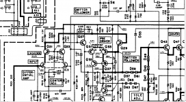
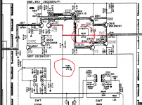
Please look at the line stage in the pic attached ... don't you see a little redundancy ? To have a line stage for me either the line input amplifier or the line output amplifier(maybe with stage gain reduced) would be more than enough to make a nice line stage.
I do not see the need of all these stages one after the other ... just that
Just think if the sound out of just one stage were better ... is not this electronic design perversion ? 🙄
To be completely fair some time ago i try to provoke some cloning activity here in the forum
I got comments like ... it is too simple to sound good (?) It does not excite my fantasy (?) ... it is too basic (?) ... it is old school design (true) ... ecc. ecc.
I also tried to sim it and i think i got nice and promising results (i am not sure about that by the way)
After having some exchange about smps i am buying two 48V smps by Meanwell ... and asa i will have free time i would like to try some prototypes following this schematic
I do not know if the Rotel line stage schematic can work also powered by a single supply ... and anyway it is more complex ...
Thank you sincerely again for your very kind effort but many issues you raise are out of my reach ... unfortunately I am not proud to be stupid at all
Attachments

Last edited:
- Home
- Member Areas
- The Lounge
- Overengineering in audio equipment