It's been very little for several months. In fact I haven't really worked on any spare time (audio) projects for some time, mainly because I moved to a new house recently.
I will take a new look at it and try to figure out a way to make it available, perhaps as a bare board solution.
I will take a new look at it and try to figure out a way to make it available, perhaps as a bare board solution.
It's been very little for several months. In fact I haven't really worked on any spare time (audio) projects for some time, mainly because I moved to a new house recently.
I will take a new look at it and try to figure out a way to make it available, perhaps as a bare board solution.
Nice
I have been using one RTX6001 as my reference DAC as well, it is fantastic! Is anyone interested in giving up theirs? A school might be interested in using it.
I was also wondering whether a ground loop breaker might be useful to handling some of the issue I remember people reporting somewhere.
I was also wondering whether a ground loop breaker might be useful to handling some of the issue I remember people reporting somewhere.
Dear Jens,
is there any possibility to add SPDIF IN/OUT to the XMOS PCB, so that I can use the superb analog performance of the RTX in conjunction with other digital Interfaces to the Host PC. The RTX would act as SPDIF->analog and analog->SPDIF converter. No interaction via USB (maybe for fs-setting, if needed).
I have added your USB -> SPDIF output mod, which is very well documented, but the above-mentioned setup is a totally different application ;-)
Kind regards
It probably can be done, but it is not straight forward. The XMOS PCB would have to be disconnected and the new interface connected to both of the internal IDC connectors. Obviously not supported by RTX.
Ok, thanks. So I'll have to skip this route.
You can always use a PC (a robust fanless thin client with PCI slot for 20 euro in DE), an SPDIF IN/OUT interface, and build a duplex loopback in linux. RTX has full USB-audio support in kernel 5.8. E.g. this soundcard Infrasonic Quartet PCI Soundkarte in Berlin - Lichtenberg | eBay Kleinanzeigen is ideal for this purpose (duplex SPDIF IN/OUT, clock-in Fs/256Fs if needed, full support in linux).
DAC Section with AK4497
From the presentation of RTX new DAC were presented, such as AK4493 & AK4497.
So I thought of making a reverse enginneered on Jen's DAC pcb with AK4497.
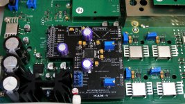
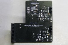
As you can see at the attachments, a prototype pcb has made with the upper part of pcb include the dac chip and the two trimmer resistors of the LPF outputs.
At the bottom there are 5V reg and the LPF sections with OPA1656.
The voltages that AK4497 needs are 5V, 3.3V and 1.8V (via external reg or internal AK4497 LDO).
For the 5V reg, I used a LT3042 configuration.
The 3.3V voltage comes from the 26pins direct and give the input voltage to the 1.8reg (ADP-150).
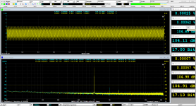
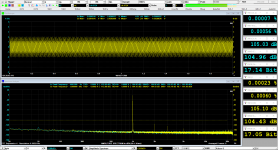
Unfortunately, I have a problem with the THD on L/R channels, that depends with the clock family.
For example, If I set the gen with 44.1K, 2V output (balanced), the THD is 0.00025%/0.00007% (L/R), if the sampling change to the 48K with the same amplitude, the THD is 0.00007%/0.00023% (L/R).
Another problem that I saw yesterday, is the low voltage output of the DAC at high levels. At low dac output levels, the differential output is almost the same between 4490 and 4497, for example with -17dB signal the 4490 has 137mV almost and the 4497 has 140mV.
But, if the level is 0dB, then the 4497 gives a much less voltage, I took almost 1.38Vrms on 4490 and 0.99 only on 4497!
Both of them have the same voltage reference (5V).
I have done some experiments for these issues, like ACKS (H/L set), HLOAD (H/L set), (DIF0-DIF1-DIF2 in combination with TDM0) but with no success.
I am quite sure that the problem is held on digital part, I took a THD measurement on DAC differential outputs and the THD had the same issue.
Any suggestion from someone familiar with the 4497 circuit will be welcome.
From the presentation of RTX new DAC were presented, such as AK4493 & AK4497.
So I thought of making a reverse enginneered on Jen's DAC pcb with AK4497.
As you can see at the attachments, a prototype pcb has made with the upper part of pcb include the dac chip and the two trimmer resistors of the LPF outputs.
At the bottom there are 5V reg and the LPF sections with OPA1656.
The voltages that AK4497 needs are 5V, 3.3V and 1.8V (via external reg or internal AK4497 LDO).
For the 5V reg, I used a LT3042 configuration.
The 3.3V voltage comes from the 26pins direct and give the input voltage to the 1.8reg (ADP-150).
Unfortunately, I have a problem with the THD on L/R channels, that depends with the clock family.
For example, If I set the gen with 44.1K, 2V output (balanced), the THD is 0.00025%/0.00007% (L/R), if the sampling change to the 48K with the same amplitude, the THD is 0.00007%/0.00023% (L/R).
Another problem that I saw yesterday, is the low voltage output of the DAC at high levels. At low dac output levels, the differential output is almost the same between 4490 and 4497, for example with -17dB signal the 4490 has 137mV almost and the 4497 has 140mV.
But, if the level is 0dB, then the 4497 gives a much less voltage, I took almost 1.38Vrms on 4490 and 0.99 only on 4497!
Both of them have the same voltage reference (5V).
I have done some experiments for these issues, like ACKS (H/L set), HLOAD (H/L set), (DIF0-DIF1-DIF2 in combination with TDM0) but with no success.
I am quite sure that the problem is held on digital part, I took a THD measurement on DAC differential outputs and the THD had the same issue.
Any suggestion from someone familiar with the 4497 circuit will be welcome.
Attachments
for example with -17dB signal the 4490 has 137mV almost and the 4497 has 140mV.
But, if the level is 0dB, then the 4497 gives a much less voltage, I took almost 1.38Vrms on 4490 and 0.99 only on 4497!
Your project is very interesting, thanks for sharing. -17dB <-> 137mV means 0dB <-> 0.97V. Are your measurements really correct?
Your project is very interesting, thanks for sharing. -17dB <-> 137mV means 0dB <-> 0.97V. Are your measurements really correct?
Hmm, you have right

I haven't seen until now with a calculator.
From the page RMS Voltage Calculator - Electrical Engineering & Electronics Tools
I see that for 2.8Vpp the Vrms is almost 0.99mVrms....so the AK4497 is right!
The datasheet of 4490/4497 says that the equation of maximum signal voltage output is : ±2.8Vpp x (VREFHL/R − VREFLL/R) / 5.
This is exactly 2.8Vpp or 0.9899Vrms when the VrefHL is 5V.
Wrong "bell" for the output of 4497!
The Jen's 4490 has 4.90Vdc rail on VrefH-L/R, so ±2.8Vpp x (4.90 − 0) / 5 = 2.744Vpp or 0.97015 Vrms .
I took again a new measurement on 4490 and voila I had note wrong on my notes about it. The voltage was 0.9690-0.9708 depending on the differential measuring branch.
In conclusion, there is no any issue with the dac voltage output, the only problem is with the THD on L/R channels when you changed the sampling family clocks.
Hi Manolis,
Very interesting!
Good work Manolis! I hope you will found out why the output of the 4497 too low.
Cheers, E.
Thanks Ghianni and Edmond for acceptance of the project.
Hmm, you have right
I haven't seen until now with a calculator.
From the page RMS Voltage Calculator - Electrical Engineering & Electronics Tools
I see that for 2.8Vpp the Vrms is almost 0.99mVrms....so the AK4497 is right!
The datasheet of 4490/4497 says that the equation of maximum signal voltage output is : ±2.8Vpp x (VREFHL/R − VREFLL/R) / 5.
This is exactly 2.8Vpp or 0.9899Vrms when the VrefHL is 5V.
Wrong "bell" for the output of 4497!
The Jen's 4490 has 4.90Vdc rail on VrefH-L/R, so ±2.8Vpp x (4.90 − 0) / 5 = 2.744Vpp or 0.97015 Vrms .
I took again a new measurement on 4490 and voila I had note wrong on my notes about it. The voltage was 0.9690-0.9708 depending on the differential measuring branch.
In conclusion, there is no any issue with the dac voltage output, the only problem is with the THD on L/R channels when you changed the sampling family clocks.
It would be easier to use the ak4493, smaller & different layout but an family improvement/step upgrade..
My 2 cents
Hp
The 4497 in datasheet is very interesting chip without to be completely expensive like 4499 (now of course all the AK chips are difficult to find!)
If this project goes with no success, then I will redesign the pcb for the 4493 sure.
4493 and 4497 use the same voltages and many pins have the same functionality...
But for me, it is very-very strange to reverse the THD of the channels depends which family clock is presented.
It is challenge to me to find the solution, independed if this project not go well.
- Home
- Design & Build
- Equipment & Tools
- DIY Audio Analyzer with AK5397/AK5394A and AK4490