You may consider reducing input gain to unity and use a single Li-Ion-battery as a supply. This one will last ages compared to the 9V block.
I would confirm layout considerations given by JMFahey. Normally I use traces of 0.6mm with a distance of 0.2mm. At critical locations 0.4mm traces. SMD-0805 per default. No need for extra tiny things - this is not a smartphone.
I would confirm layout considerations given by JMFahey. Normally I use traces of 0.6mm with a distance of 0.2mm. At critical locations 0.4mm traces. SMD-0805 per default. No need for extra tiny things - this is not a smartphone.
Last edited:
Congratulations.
Now that you are in the last leg of your design, 3 suggestions:
1) 10X/20dB gain in the first gain stage is too much, you will clip and have no way to control that since gain pot is after it.
Suggest you use 4X or 5X TOPS, and that because of the 18V supply.
If you had used a 9V supply, no more than 2X or 3X TOPS would be advisable.
2) you connected Baxandall tone control net straight to volume pot wiper.
It is advisable to insert a cap between them (think 1 to 10uF), or your Bass control will allow almost 20dB *DC* gain for no good advantage.
Or to see it from other point of view, maximum Bass boost goes down to DC ... who wants that?
3) didn´t check PCB connectivity, but you left too little "useful" copper.
You can use WAY wider tracks almost everywhere, there is a lot of free space available.
Not for "electrical" reasons, current is nil, but mechanical ones.
And etching ones: if you etch your own boards a grain of dust, a small bubble , a small toner pinhole, a scratch or small almost invisible crack can ruin your day.
And leave a more substantial copper ring around each hole, doubly so on those receiving wires.
I'll adjust gain according to pickup to get somewhere medium to high output, something slightly below by max accepted by most amps.
Since the cap between the Vol pot and the tone ciruit will need to be of that value, and those are pretty big not sure there will be enough room for another, and on top of that i already have 500k passive volume i might just as well stick to that option. Volume between the pickup and the circuit, my existent basses are all like that and no issue as i almost never use anything lower than 100% vol on the instrument.
Good idea on the trace width, you couldn't be more right. I work on it zoomed in 5-10x and wasn't even aware it's actually going to be that narrow in actual size
 . I'll post image of wider trace.
I commercially make MI amplifiers and *try* to use 40 to 50 mil tracks or wider wherever possible (try to avoid necking down to less than 30 mil) and 100 mil pads, go figure.
Musical Instruments and their amplifiers tend to be carried around and bumped a lot by their very nature.
And IF you want to tweak your design later (I bet you will 🙂 ), thin copper makes for easy to damage or destroy pads and tracks, so make it robust from the beginning.
All on point 🙂
Please keep us updated with your build and treat us to a couple tasty solos or scales. 🙂
You got it, just need to finish the bass as well, that's also an ongoing project

Immense thanks for your thoughts and input, very appreciated.
Yeah, that's a tidy piece of work -- very nice.
Thanks Rick, this is possible with the help of the people here and yourself
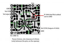
Only found one oopsie-doodle. (Assuming I have the layout sorted correctly), it looks like the Vol pot ground return connects to battery Gnd, rather than the TLE2426-provided *Signal ground*. IIRC we were expecting to eliminate some power-on/off thumps and capacitor coloration w/that little trick -- since it allowed removing both coupling caps.
That GND pad will be used for signal, the Vol CCW pad is diagonally on the other side on the ground you suggested from the TLE, i've attached an image with pad description. So there's no need for the coupling caps cause of that, ok good to know.
I'd stick with the 470n supply bypass capacitors, as long as there is room for them. They are serving double duty, after all. Also, it will keep us farther from the 'unstable' part of the graph in Fig 17 (a couple posts back -- #76 maybe).
Got it. Yup there is enough room for 4x 470n 25V basic ceramc caps so i'll use 470n in that case, they are available in 0805. The OPA145 suggests low ESR ceramic caps, but not sure i can find low ESR SMD ceramic, found only the generic ones, i guess that shouldn't be a huge issue... ?
Something else that deserves mention: The 4-capacitors in the tone circuit should be film of some sort, not ceramic. Other members know these types better than I, so best leave it to them.
I got all film caps, high ripple current electrolitycs, RG resistors, all recommended with lowest moise/coloring for audio by people in here and other threads i stumbled upon. Not the cheapest components but tried to keep it under reasonable balance price/sound quality.
I'd say, 'Go ahead and order the board', 'cause I'm pretty sure it'll work (with the Volume pot CCW connection fix). If a problem does come up, hop back on and we'll sort it out.
I will likely make it myself on laser printer. Ordering small quantity atm is expensive, i had a look. Let's see how's gonna turn out.
Generally, I'd like to see shorter traces for gain-setting dividers and virtual-ground inputs. But it certainly isn't worth setting aside your work so far.
Will this make a huge difference? As the board is so small the longest route is probably 2-3cm.
Here's an image with some description and updated trace width for easier work.
Attachments
You may consider reducing input gain to unity and use a single Li-Ion-battery as a supply. This one will last ages compared to the 9V block.
I'll play with the gain accodring to the pickup, it could be unity though i don't know yet.
As for batteries, i'm using 2x Lithium 9V ones. With the usage this preamp will have and the roughly calculated total current consumption, it should last at least a year i guess.
I would confirm layout considerations given by JMFahey. Normally I use traces of 0.6mm with a distance of 0.2mm. At critical locations 0.4mm traces. SMD-0805 per default. No need for extra tiny things - this is not a smartphone.
Haha yup it makes sense just wanted to keep it as small as i could, it is so cool at the end when it's so small but it can actually perform like crazy haha
 . Did the mods JMFahey suggested, thanks for your thoughts Bucks
Just as a practical example, this is the Tracks side of a 2 x TDA2030 amplifier.
Most tracks are 40-50 mil (thousandths of an inch, the old "Imperial" PCB standard) or 1-1.25mm :
Why? ... because there´s ample space, that is!
Thinner ones (passing between chipamp pads) are 30 mil (0.75mm)
Pads are 100 mil (2.5mm)
Rectangular copper blocks have been added at various points, specially ground.
This is a very easy to print, toner transfer, etc. PCB and very forgiving of errors.
Might update it with an automated copper fill , this one is about 15 years old and designed using oooolllddd Protel Autotrax or Tango PCB .
Both DOS based, go figure, I have been using them since 1989 😱
Still keep a Windows XP "workstation" he he, just for old software which still works flawlessly (Corel Draw 5 for front panels, Micros*ft Works customer database, etc.)
Always silkscreen own boards (and panels) in-house so no need for modern Gerbers for China fabrication.
For prototypes, toner transfer and quick etching give me a drilled board in less than an hour .... try to beat that PCBWAY or JLCPCB!!! 😛
Cost? U$47 buys a 3 x 4 FEET single layer phenolic raw board. 😱
Attachments
Ok I know what you mean now. I use DipTrace, I'll try extra widening where possible to see the outcome. I'll post the result.
I ordered the additional components, also waiting for the drill bits to arrive. Planning to use 0.36-0.4mm for vias, 0.6mm for through hole components and 0.8mm for wires.
I used to do electronics a looong time ago, by now have forgotten plenty of stuff, this is a good refreshener. I used to trace many boards by hand with permanent marker and ruler, some of them really complicated with up to 60cm long PCB's with processors on them, but I don't have them by hand to post :/. Cause haven't done anything recently I feel like a toddler in electronics now :B
All those are good tips and trouble savers, thanks again 🙂
Last edited:
Ok, so finally I assembled this on a factory made PCB. Made few PCB's at home, didn't turnout bad but since it's so small I wanted the nice factory finish.
Plugged in everything, same setup as with the test circuit, no singal input, and it "sounded" normal. I could even hear slight RF with volume on the amp all the way up which gave me the impression that the preamp works in some way. (as a note, the test circuit didn't have the TLE and different opamps were used)
10-15 sec after being powered on, everything connected just no signal running, the TLE literally got toasted with smoke coming out if it. The slight RF dissappeared. Had a look at the TLE and yes, it's fried. Powered by 2x 9V batts in series. Then I noticed cause I didn't use vol pot for testing, I forgot to jumper it, so there was no connection between the output on the first opamp and the tone circuit input. It doesn't seem like this could've caused this, or could it?
The PCB was electrically checked in the factory, I made sure I used the right components in the right spots, made sure to do clean soldering.
I'm confused. Any thoughts?
Starting with basics, smoke/toast mean (too much) power dissipated which means voltage times current at the smoked component.
In theory we know the voltages so follow traces or actual wiring to find what might be eating that much current.
An inverted electrolytic perhaps?
An Op Amp will pull current straight from +18V rail, not from the half rail, although a solder bridge will destroy anything if at an ugly place.
A jeweler´s loupe is your friend.
Just today I had to deliver a 100W Bass head and could not because preamp voltages were slammed to the -15V rails.
After 15 angry minutes I run a solder bead along the +15V rails and everything came back to normal, obviously there was an *invisible* crack "somewhere" along that long track.
Invisible to my tired eyes at least.
Meaning: sh*t happens and often when you are in a hurry.
A.K.A Murphy´s Law
Last edited:
Darn. Mighty sorry to hear that. 😡
Do you have a bench supply to try 5 to 8V, with current monitoring -- or even a hard limit? Your lithium 9V-ers must be a lot stronger than 'normal' 9V batteries -- I'd be surprised if they could provide the current to release the magic smoke.
Start by removing the dead TLE; a pair of 4k7 to 47k resistors (or about any other values that you have two of) can provide temporary replacement for further troubleshooting. Then we'll need to see some voltages.
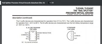
The demodulated RF that stopped when the TLE popped suggests oscillation. I'll review the spec PDF for it.
Regards
Do you have a bench supply to try 5 to 8V, with current monitoring -- or even a hard limit? Your lithium 9V-ers must be a lot stronger than 'normal' 9V batteries -- I'd be surprised if they could provide the current to release the magic smoke.
Start by removing the dead TLE; a pair of 4k7 to 47k resistors (or about any other values that you have two of) can provide temporary replacement for further troubleshooting. Then we'll need to see some voltages.
The demodulated RF that stopped when the TLE popped suggests oscillation. I'll review the spec PDF for it.
Regards
I'll go over the rails and traces and all components to check them manually with a multimeter, visually nothing seems to be shorted and I tried not to overuse solder.Starting with basics, smoke/toast mean (too much) power dissipated which means voltage times current at the smoked component.
In theory we know the voltages so follow traces or actual wiring to find what might be eating that much current.
An inverted electrolytic perhaps?
An Op Amp will pull current straight from +18V rail, not from the half rail, although a solder bridge will destroy anything if at an ugly place.
A jeweler´s loupe is your friend.
Just today I had to deliver a 100W Bass head and could not because preamp voltages were slammed to the -15V rails.
After 15 angry minutes I run a solder bead along the +15V rails and everything came back to normal, obviously there was an *invisible* crack "somewhere" along that long track.
Invisible to my tired eyes at least.
Meaning: sh*t happens and often when you are in a hurry.
A.K.A Murphy´s Law
Yeah you're right, that's why kids don't want to play with Murphy
I was surprised too that batts can do that. I don't have any adjustable power supply, the only way I can measure voltage or current is by multimeter. I can use single 9V, I bought cheap standard alkalines now... Hah.Darn. Mighty sorry to hear that. 😡
Do you have a bench supply to try 5 to 8V, with current monitoring -- or even a hard limit? Your lithium 9V-ers must be a lot stronger than 'normal' 9V batteries -- I'd be surprised if they could provide the current to release the magic smoke.
Start by removing the dead TLE; a pair of 4k7 to 47k resistors (or about any other values that you have two of) can provide temporary replacement for further troubleshooting. Then we'll need to see some voltages.
The demodulated RF that stopped when the TLE popped suggests oscillation. I'll review the spec PDF for it.
Regards
As for the oscillation not sure how it works, the circuit seemed and "sounded" very normal before the TLE blew. The RF was barely audible, I've heard the same thing with the other all discrete circuit I've built, but without the TLE. Both sounded the same in that regard just nothing blew up in the transistor one.
I'll make the resistor divider. Where should I measure voltages?
Last edited:
Umm .. so sorry I didn't notice sooner 😱 -- I think the TLE might be in backwards, with power being applied to the Output terminal. So hard getting used to viewing pinout drawings shown Top View. Sorry. 😱
Since this is a micro-power circuit, let's also put a current-limiting resistor in the battery lead -- just temporarily. 470 or 1k would do; 330 or 1k5 OK, too.
We'll consider voltages to measure, once part-faces aren't blowing off.
Best(better) luck 😉
Since this is a micro-power circuit, let's also put a current-limiting resistor in the battery lead -- just temporarily. 470 or 1k would do; 330 or 1k5 OK, too.
We'll consider voltages to measure, once part-faces aren't blowing off.
Best(better) luck 😉
Last edited:
That's ok, I understand 🙂Umm .. so sorry I didn't notice sooner 😱 -- I think the TLE might be in backwards, with power being applied to the Output terminal. So hard getting used to viewing pinout drawings shown Top View. Sorry. 😱
Since this is a micro-power circuit, let's also put a current-limiting resistor in the battery lead -- just temporarily. 470 or 1k would do; 330 or 1k5 OK, too.
We'll consider voltages to measure, once part-faces aren't blowing off.
Best(better) luck 😉
Ok, i'll put 1k resistor in series with the battery in the positive terminal.
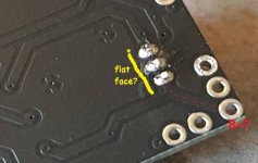
I know sometimes components can be tricky to orientate, but are you sure the power goes to the output terminal on this one? I've connected it as in the image below. Just without the cap...

Yup, still purdy sure ..
And that board is so pretty, too!
Hopefully this is the only oopsie-doodle.
Cheers
edit: Not that the power is supposed to go to the Output terminal -- but that it IS with the TO-92's flat face facing that direction.
And that board is so pretty, too!
Hopefully this is the only oopsie-doodle.
Cheers
edit: Not that the power is supposed to go to the Output terminal -- but that it IS with the TO-92's flat face facing that direction.
Attachments
Last edited:
Thanks 🙂Yup, still purdy sure ..
And that board is so pretty, too!
Hopefully this is the only oopsie-doodle.
Cheers
edit: Not that the power is supposed to go to the Output terminal -- but that it IS with the TO-92's flat face facing that direction.
The markings on the photo are correct, its orientation and B+. The IN is connected to the B+ terminal.
So I should flip it, to connect output to B+... I have one more to try, after this is purchasing more :O
If you take a look at it where it's burned, it's exactly between the IN and COMMON pins, this makes sense I guess with what you're saying.
View attachment 866141
Last edited:
A series resistor in the supply rail always is a good idea. This prevents burning of the opamps in case of a latchup that may be triggered by some erratic pulses. Assuming a latching current >200mA a value of 100 Ohms is sufficient, while 1kOhm could degrade output level. As a substitute for TL072 nowadays I prefer OP2196 - less noise & less power consumption for a longer battery life.
Last edited:
I already have the PCB made without those resistors so modifying it would involve making a new one. Anyway, the problem is the orientation of the TLE, flipping it solved the issue, I was reading the data sheet wrongly. The way it's given is confusing, top view with visible pins on the bottom that are not in reality, but it's written above what is the view point but I was blind apparently to see it... XDA series resistor in the supply rail always is a good idea. This prevents burning of the opamps in case of a latchup that may be triggered by some erratic pulses. Assuming a latching current >200mA a value of 100 Ohms is sufficient, while 1kOhm could degrade output level. As a substitute for TL072 nowadays I prefer OP2196 - less noise & less power consumption for a longer battery life.
The OPA2196 has pretty good specs for battery performance, but it's a CMOS architecture, I want FET for an instrument preamp. I'm not using the TL072, the opamps are OPA145, FET with each 0.45mA with somewhat better specs in the other areas too. You should check them out, pretty new on the market.
Rick, you were right, I was looking at the TLE package in the datasheet the wrong way. It even says on it what's the point of view, I was just paying attention only that much not to see it, and the illustration is deceiving on this one..
Anyway, flipping it works like a charm it performs beautifully, just need to tweak the tone control a little. Before figuring that, I did some testing with 2x 43k resistors splitter, measured the current draw on the circuit and the results seem somewhat unusual I think.
With 2x 43k rail resistors, the current draw on the circuit is 0.98mA on 9V, and 1.1mA on 18V, which is perfect and expected since the opamps only together are about 0.9mA.
With the TLE though, the current draw is 3mA on 9v and 3.3mA on 18V, while the TLE is supposed to consume about 0.17mA on 5V, 9V definitely wouldn't increase the current consumption by about 2mA......
Last edited:
That does seem a little high -- perhaps there's an oscillation ..?
How much total capacitance is on the TLE's Output pin, as built?
Do you know of a 'scope you could borrow? Or maybe a friend's bench you could hike it over to?
How much total capacitance is on the TLE's Output pin, as built?
Do you know of a 'scope you could borrow? Or maybe a friend's bench you could hike it over to?
Could be. Hmm, it could be a bit difficult to get my hands on an oscilloscope, I don't know anyone around me dealing with electronics... If it turns to be that much needed the only option is to buy something cheap I guess, later I may use it for other projects but would have this as the last option if possible
Total capacitance is 1uF on each rail towards Output
So it oscillates with the TLE but it doesn't with resistors..
I just read some more details about the OPA145, it says it needs decoupling caps near the opamp with high impedance power sources, which is the resistor splitter, and it doesn't seem to oscillate that way since the current draw is on point. But the TLE is very low impedance so lowering the caps or eliminating them my fix this if the TLE is to be used...kind of makes sense, I can try this easily
Last edited:
- Home
- Live Sound
- Instruments and Amps
- Component suggestion for a preamp please