This is complete nonsense. Is a cd player "normal"? Redbook CD is 2V out single ended (unbalanced) thus 4V out balanced. All the "normal" stuff I have at home in a "normal" "home stereophonic music reproduction system" is connected to my preamp using balanced outs and xlr cables and is putting out 4v into my preamp. My dac output is (at least) 4V balanced, my cd player output is 4V balanced, my minidsp same. Stop this nonsense, 2V single ended and 4V balanced is standard, Sony/Philips "redbook" specs for the cd medium, issued 1980, specified a "full scale" output for cd players of 2 volts. That would be for unbalanced outputs, and would correspond to 4 volts balanced, as tested in the review.
Never mind.
You're simply confusing "input voltage" and "output voltage"; as said before, using an input voltage of "4 Volts" is sound (because of the gear you've mentioned as an example) but using "4 Volts" output voltage is not reasonable for the reasons I've mentioned. At least not, if used exclusively for the measurements.
Still doesn't make sense. If it's in the spec, is should work, surely. If it's not reasonable to use it at that level, why is is specced for it? Especially as plenty other - cheaper - units are fine under those conditions.
It does 'work' just not as well as at lower output voltages. I checked the parasound website and the spec doesn't quote the output level at which the THD+N figures are met. It says maximum output is 9V but not the distortion levels.
Still doesn't make sense. If it's in the spec, is should work, surely. If it's not reasonable to use it at that level, why is is specced for it? Especially as plenty other - cheaper - units are fine under those conditions.
As billshurv already wrote, "work" and "work at best" are different things.
"Doesn't make sense"? It's funny, because my stance on it is that, if your trying to do measurements on a unit it should be your goal to characterize the device as good as possible, means show the strengths and the weak points.
I agree. It is important to know if a preamp wont drive an AHB2 on low gain setting, but most benchmark owners are likely to partner with the DAC3 or at pro levels.
Never mind.
You're simply confusing "input voltage" and "output voltage"; as said before, using an input voltage of "4 Volts" is sound (because of the gear you've mentioned as an example) but using "4 Volts" output voltage is not reasonable for the reasons I've mentioned. At least not, if used exclusively for the measurements.
As usually, you are rather political than strictly technical. Your game is not fair enough. There are many amplifiers that need more than 2V to get full power. One of them is Passlabs X600. 600W into 8ohms, gain 26dB. You need about 3.5V input to get rated power.
For any competent designer, there is no problem to keep all parameters up to 4V. Especially if the preamp works with 2 x 100V supply voltage, as JC2 does. This preamp behaviour is a big disappointment to me. I heard it several times, but never measured.
Attachments

How about we talk about the advantages and disadvantages of high gain, high voltage pre amps coupled to voltage follower power amplifier 😉 Project 83 - MOSFET Power Follower
Pavel,
What would the loudspeaker's contribution to the system distortion be at 600 watts?
With a 26 dB gain amplifier capable of 600 watts output I would expect the operation "sweet spot" to be under 400 millivolts on recorded music and under 40 millivolts for live music. Although I can't image the Pass amplifier to be used for live music.
I am pretty sure you have figured out audio product design has changed as knowledge base has increased and better parts are available. Of course there are still those who prefer to use parts such as Allen Bradley 1/2 watt hot molded carbon composition resistors.
Also pretty sure your reference is live symphonic music. Can you talk the same language as a heavy metal fan? (Would you even want to?)
I am of the opinion that the review that started this tangent had accurate measurements of unusual operating points. I don't consider this surprising. As you may be aware there are many people who mix and match components to get what they perceive as better results. Conversely one can mix system components to get horrible results!
I did "fix" one very expensive system that quite simply did not reproduce music even acceptably, just by shortening the moderately expensive loudspeaker cable from a few hundred feet to the minimum length required. A rather surprising improvement to all involved! Who knew a little bit of wire could make a major difference! (Well anybody with basic knowledge. It is in the AES standard the cable impedance should be less than 5% of the loudspeaker's.)
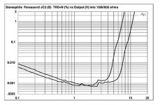
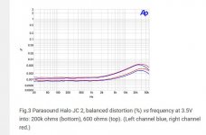
Pavel: up to 3.5V the JC2 is pretty good it's above that the issue is seen. Attached are a couple of graphs from stereophile. which show its a 4V the discovered problem appears. I'm not justifying the fact it was missed just saying it's unlikely to cause an issue very often. LM4562 on 17V supplies will remain clean up to +27dBu with no issues (other than it's habit to pick up 2GHz radio broadcasts).
Attachments
I am really tired of that 4V discussion. I gave just one example of the 600W/8ohm/26dB amp, which in facts goes well above 600W, so you need more than 3.5V then. Please let's not discuss the power amp distortion. I do not take it. There is no reason for a properly designed preamp to give 4V at full specs. It is no problem to make a preamp which gives 18Vrms output in perfect quality. There should be no excuses.
I guess that I should comment, even though I have not yet found the exact cause or the exact solution to this problem with the JC-2.
Of course, the most important criticism is why this was not found and dealt with before, perhaps 10 years ago. Well, when we normally test preamps, we usually turn them up to maximum, then lower the drive voltage accordingly, in order to maximize the S/N ratio by removing the noise contribution of the volume control. This was done by both me and John Atkinson, apparently, so the distortion increase disappeared from the measurement.
This appears to be a problem when the volume control is adjusted to the level that maximizes its resistance as seen by the input of the complementary differential jfet input stage of the JC-2. Then an added distortion mechanism is introduced. In normal operation, as I have normally used, over the years, neither the maximum output would exceed 2V and usually much less than this, and the gain would be reduced significantly (the volume control would be turned down significantly) and this problem would be almost unmeasurable, and most likely inaudible. That is why it was not found earlier. Even in its worst case mode, I personally doubt that it would audibly change the sound quality much, but it is a measurement embarrassment, none the less. Can it be fixed? Probably, we shall see. Is it worth fixing? Probably not, for most applications.
For the record, the Atkinson measurement is the mostly likely useful example, even though it is at 3.5V output, too much for my amps, that is for sure.
Never mind.
You're simply confusing "input voltage" and "output voltage"; as said before, using an input voltage of "4 Volts" is sound (because of the gear you've mentioned as an example) but using "4 Volts" output voltage is not reasonable for the reasons I've mentioned. At least not, if used exclusively for the measurements.
It's the same, 4V output balanced (or 2V "per leg" as Parasound specs balanced inputs/outputs) means 2V unbalanced. There are plenty of power amps that need more than 2V to get rated power. Nowadays people are ditching preamps as they hook up their dac directly to a power amp via xlr, which is a normal usecase.
Furthermore if you apply 2V/4V of input voltage (fully modulated source) to a unity gain preamp at full volume what would you expect to measure as output voltage?
Last edited:
. There are plenty of power amps that need more than 2V to get rated power. Nowadays people are ditching preamps as they hook up their dac directly to a power amp via xlr, which is a normal usecase.
Nowadays? My Marantz CD80 had a motorised volume control to bypass the preamp. In your normal use case the preamp is either in the dac or digital volume control is used. How many people run unattenutated out their DAC into their power amp ?
Not trying to wind Pavel up here but I see very few cases in domestic audio where the gain structure is optimal for this. Maybe will change over time?
Last edited:
Correct, the 210 cabinets.Those appear to be a pair of classic Altec A4 Voice of the Theater bass bins, minus the "wings"
Yes, those you see were temporary Pyles. I upgraded them to some beefy Seleniums for power handling.although it looks like the woofers have been upgraded?
Yes, I have quite a few pieces.What's the story on those bad boys, Cal? You are definitely an Altec-aholic, heh!
Yes, those you see were temporary Pyles.
I'm so very glad to hear it
Speaking unbalanced I think the current "normal" gain structure is not optimal as well. If I remember well Parasound specs its power amps with 1V input sensitivity, assuming same b rand preamp+amp I would like to know the volume position that clips the amp with a fully modulated source (preamp at unity gain, leave alone the 14dB maximum gain). To do it at home: just record a cd with a 0dB sine wave signal and play it into the preamp+amp combo turning up the volume until you hear clipping. Like at 10/11 hours volume position?
Well, when we normally test preamps, we usually turn them up to maximum, then lower the drive voltage accordingly, in order to maximize the S/N ratio by removing the noise contribution of the volume control. This was done by both me and John Atkinson, apparently, so the distortion increase disappeared from the measurement.
Please bear with me, the schematics from the past show a 10K volume control pot. The situation without any more knowledge would be that to get pass through operation at 4V you turn the pot down to attenuate by the same amount as the fixed gain. At 20dB this would mean ~0.4V at the input with ~1K input resistance. I don't see this causing that much distortion simply due to the input capacitance modulation especially since Vgd is relatively high. The SK170/SJ74 pair has values for the capacitances on the data sheet and they obey the theoretical 1/3 power law, for this effect simulation will give reasonable results.
All DAC chips I worked with have digital output control.
My preferred routing for active speakers is digital in, DSP crossover, followed by 1 DAC per driver, all output DAC's digitally controlled by means of a single 1 Euro potmeter.
My preferred routing for active speakers is digital in, DSP crossover, followed by 1 DAC per driver, all output DAC's digitally controlled by means of a single 1 Euro potmeter.
Can't my volume pot is digital with about 50 turns.To do it at home: just record a cd with a 0dB sine wave signal and play it into the preamp+amp combo turning up the volume until you hear clipping. Like at 10/11 hours volume position?
output DAC's digitally controlled by means of a single 1 Euro potmeter.
Fine, but if you have too much gain in your power amp you have to chuck 4 bits away just to preserve your hearing/drivers/marriage. Some people angst over that 🙂
- Home
- Member Areas
- The Lounge
- The Black Hole......