...The author claimed fast, firm and controlled bass. In order to prove this, simulated tone bursts were displayed in th article. It was not at all hard to replicate these tone bursts in LspCad by simply mimicking the transfer function of the woofer....
It seems to me to be impermissible to use a simulation based on a theory to prove the theory.
The contention, all but universally shared by MFB builders, is that MFB really does get the cone to respond stronger to transients than any mere EQ would provide.
B.
I am doing some tests right now, with Mini DSP first and after that I have two feedback loops. The inner feedback loop with current driving (transconductanse amplifier) and the outer MFB loop.
The inner loop gets rid of some distortion, and also provide you with a grater phase margin so that you can get more MFB without oscillation.
1+1=3
The inner loop gets rid of some distortion, and also provide you with a grater phase margin so that you can get more MFB without oscillation.
1+1=3
I agree. There are three kinds of feedback, according to the sensor it relies on : amplitude, velocity and acceleration. Each acts on the parameters of the driver in its box and therefore on the frequency response. The "impulse" response depends on the frequency response.The "better impulse response" claim makes me suspicious: The impulse response has nothing to do with motional feedback as such : it is a bandwidth dependant parameter.
Last edited:
I am doing some tests right now, with Mini DSP first and after that I have two feedback loops. The inner feedback loop with current driving (transconductanse amplifier) and the outer MFB loop.
The inner loop gets rid of some distortion, and also provide you with a grater phase margin so that you can get more MFB without oscillation.
1+1=3
The minidsp ( adau1701) has a latency around 1.2 millisecond so it will not work in a feedback loop.
The latency of a codec ( adc-dsp-dac) is very important if you put it in a feedback loop. Latency introduces a frequency dependant phase lag and if you pass 150 degrees phase lag you will have a unstable system. A 10uS latency will introduce a phase lag of 3.6 degree at 1 khz. Below a absolute phase measerument of a 1772 ( running at 192K) and a 1777 ( 768K):
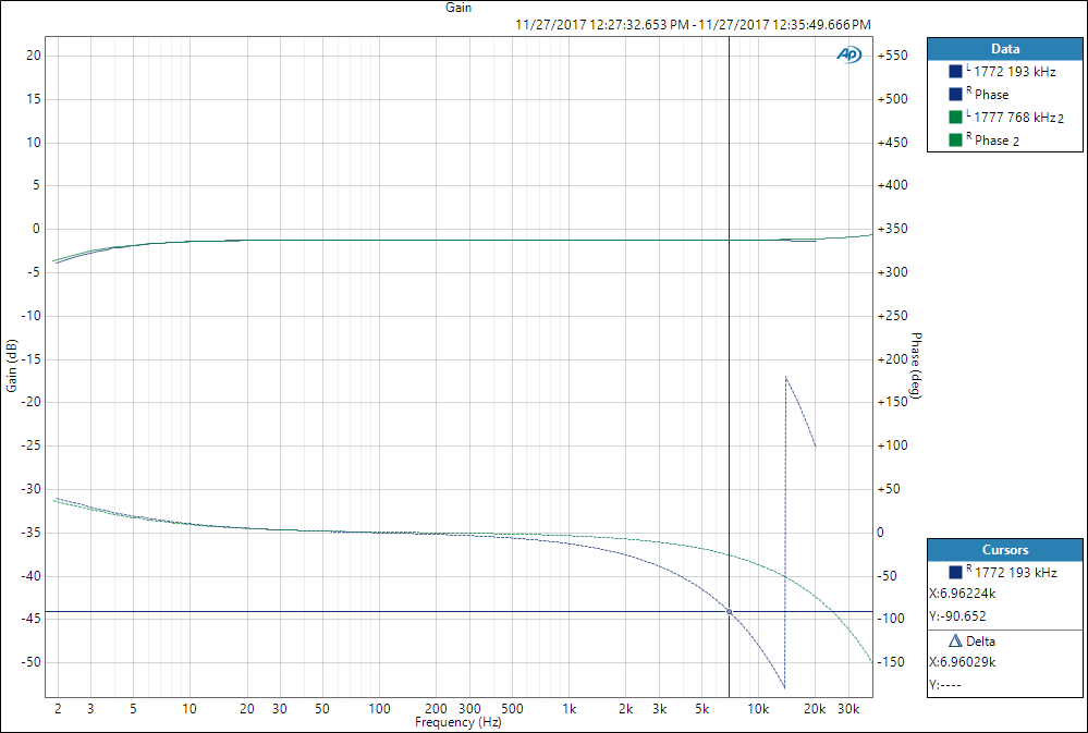
Estimated latency of the 1772 is 36uS and the 1777 10us.
What will happen if the latency is around 1mS?
Estimated latency of the 1772 is 36uS and the 1777 10us.
What will happen if the latency is around 1mS?
Attachments

My (borrowed) mini DSP is not in the feedback loop.
It´s before the feedback loop.
Sorry if I was not 100% clear.
It is used and will be used for dipole correction. But there is also plugins for compressor and limiter. To be able to play louder an cut the peaks. For safety reasons that is...
It´s before the feedback loop.
Sorry if I was not 100% clear.
It is used and will be used for dipole correction. But there is also plugins for compressor and limiter. To be able to play louder an cut the peaks. For safety reasons that is...
The minidsp ( adau1701) has a latency around 1.2 millisecond so it will not work in a feedback loop.
A DSP should be used before the feedback loop to pre-condition the signal. So you can and should do all kinds of regulation which will keep the following stage in it´s limits, prevent over driving the amp, limit upper and lower frequency, do level dependent equalization etc. Simply all the stuff you would put in front of a modern high quality sub woofer anyway. I do not see the need to reinvent the wheel here, just to turn anything complicated.
The feedback loop itself has proven to work with all kinds of analog stuff, from coils, capacitors,to optics and microphones,piezo and more advanced acceleration sensors. Where is the need to turn this digital? We are talking about 10-200 Hz maximum.
All this digital thinking leads into feed forward regulations, not feed back.
Feed forward has proven to be unrealistic in this area, as you will not be able to predict mistakes of individual speaker tolerances at reasonable cost.
This "simple" MFB has the advantage to correct tolerances and aging of any suitable woofer.
For me it is more a problem of individual fitting, but no rocket science playground for theoretical physics.
The place for DSP is inside the loop because the loop is lousy. We are really "walking on thin ice" trying to make subs with major phase and amplitude shifts inside the passband. So if you could make the loop work, that would be great.
Next question is what digital processing is fast enough to help even for a band entirely below 100 Hz? And where to get chips that are fast enough? Those two questions need answers.
B.
Next question is what digital processing is fast enough to help even for a band entirely below 100 Hz? And where to get chips that are fast enough? Those two questions need answers.
B.
Ben's question is already answered in post 145. Prof. Rob Munnig Schmidt (RMS) and ds23man have already designed working systems around the ADAU 1777 chip. The Grimm Audio mfb Sub is one example of a commercial digital RMS design/1777 implementation.
So such systems do exist and are actually working. The idea seems to be that Hypex is to market a plug and play mfb system including a current drive plate amp combined with a SEAS woofer.
So such systems do exist and are actually working. The idea seems to be that Hypex is to market a plug and play mfb system including a current drive plate amp combined with a SEAS woofer.
Look for DSP chips designed for ANC headsets (and be ready to solder BGAs 😀 )
One point which has not been discussed is the fact that all these solutions has only been applied to closed box designs. Only the ACE Bass (current drive) solution takes a vented design into consideration.
If you want high PSL at low freq, there is two ways to go. Either many more active drivers (costly), or a ported/PR design. If you want the solution reasonably small, PR is the best option in my opinion. For stereo, this is probably not such a big problem, as little material plays much below 30 Hz, but for HT it is quite essential.
So the question was why MFB is not used more often, I think this is one of the reasons.
Could you please explain what we are meant to be learning in post 145.Ben's question is already answered in post 145.
Thanks.
B.
Coda gear seems very nice.... measured at 5 cm. But then some manufacturers don't blush when they lie, so hard to tell.
Definitely sealed. MFB only works properly with sealed. Sure, you can build a ported system but it can't work right with MFB because the sound output is not tied to the cone motion. If there was acoustic feedback that worked, maybe BR could be used.
Question: Coda makes quite an effort to boast about their sensor but to hide how their sensor works. Fair enough, I suppose. They talk of velocity and electro-mechanical. That could be a sensor winding on the VC former, current feedback, or Wheatstone Bridge. Almost any MFB sensor will produce the exemplary plots they published.
Anybody guess how their sensor works?
B.
Sorry if I was unclear. Post 145 refers to the phase characteristic of the ADUA 1777 as measured by Rob Munnig Schmidt. Has been applied in real working systems, so the latency of the 1777 has been proven to be a non issue. That's all.
Theres a how it works video:
YouTube
What I don't quite understand is they talk about no need for calibration but to me there would have to be some kind of function that relates resistance to position that would be unique for each driver design. To determine that function you would have to perform some kind of calibration with a laser inferomtry setup. I do quite like how low cost, neat and durable it looks to be to integrate the sensor into the surround though.
I watched both video's. Correct me if I'm wrong, but this is how I envision the workings of the system:
1) the sensor provides a deviation in resistance in relation to the distortion of the cone. That "signal" is fed into the DSP
2) the DSP has to analyze (FFT?) the deviations over a time interval and send out a correction on the signal.
Analyzing a signal in real time and fast enough (<< 1 ms) to produce a correction signal that is still relevant in relation to the input signal requires a lot of MIPS. I have a hard time believing this is feasible.
The place for DSP is inside the loop because the loop is lousy. We are really "walking on thin ice" trying to make subs with major phase and amplitude shifts inside the passband. So if you could make the loop work, that would be great.
Next question is what digital processing is fast enough to help even for a band entirely below 100 Hz? And where to get chips that are fast enough? Those two questions need answers.
B.
The Grimm sub uses the 1772 dsp. But it is not only a story about subs, MFB is also for 2 or 3 way systems. The first prototype I build is 3 way system with a seas 10"woof. Feedback loop ends at 500Hz, used XO 350Hz. This is with the 1777. Rob has a 8" Dayton woofer running with a feedback loop stopping at 1,5Khz.
They use coil/magnet sensor, same system as using a second voice coil.
The Grimm sub uses the 1772 dsp. But it is not only a story about subs, MFB is also for 2 or 3 way systems. The first prototype I build is 3 way system with a seas 10"woof. Feedback loop ends at 500Hz, used XO 350Hz. This is with the 1777. Rob has a 8" Dayton woofer running with a feedback loop stopping at 1,5Khz.
Yeah you can make a higher bandwidth, but you often compromise bandwidth for loopgain. You can also make high loopgain at low frequencies and accept the increase of distortion in the mid frequencies due to the bode inequality. It is really the sub area where MFB shines IMO.
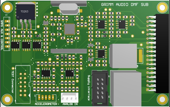
Do you know whether the internal ADC/DAC is used of the 1777? I presume external ADC/DAC add to much latency due to processing and interfacing. The PCB (as seen below ) doesn't show any ADC/DAC's either.
- Home
- Loudspeakers
- Subwoofers
- Servo controlled subwoofers - why arent they used more often