They use coil/magnet sensor, same system as using a second voice coil.
Aha! Just as I suspected (post 153).
With a long thin-wire sensor coil, you get a nice (low impedance, low RF interference) signal to drive the MFB circuitry. A good approach if you are making your own drivers.
But otherwise, it has no advantages over current or bridge feedback which also twice-chew the same magnet circuit and, as a disadvantage, there is the risk of cross-contamination of the VC and the sensor winding.
B.
I watched both video's. Correct me if I'm wrong, but this is how I envision the workings of the system:
1) the sensor provides a deviation in resistance in relation to the distortion of the cone. That "signal" is fed into the DSP
2) the DSP has to analyze (FFT?) the deviations over a time interval and send out a correction on the signal.
Analyzing a signal in real time and fast enough (<< 1 ms) to produce a correction signal that is still relevant in relation to the input signal requires a lot of MIPS. I have a hard time believing this is feasible.
OK, looks like we have a debate going on here.
Is Klippel system feedback or is it some kind of engineering fantasy that you can perfectly predict how a device will behave and thus can pre-correct it?
I'm betting on the second since it kind of fits the Klippel mind-set (and seems sadly naive to me).
B.
What they do at startup is to read out the 0 value. Then i guess thay had done excursion measurement x-max and read out min max resistance. Make a table.Theres a how it works video:
YouTube
What I don't quite understand is they talk about no need for calibration but to me there would have to be some kind of function that relates resistance to position that would be unique for each driver design. To determine that function you would have to perform some kind of calibration with a laser inferomtry setup. I do quite like how low cost, neat and durable it looks to be to integrate the sensor into the surround though.
And finally let the DSP do the nulling (zeroing) every startup and then grab the table, and do a simple adjustment.
We use the internal adc/dac of the 1772/1777 because they are super low latency. In the Grimm sub the integrator is stil analog, the dsp is only in the sensor signal. In our new design all is done within the dsp. Saves electronics and reduces noise.
Interesting to see that latency is THAT important. Grimm is quite famous for astonishing AD/DA conversion. I just didn't expect them to settle for an internal AD-DA since the THD+n is only -94dB.
I guess the "high" frequency phase shift is important to guarantee stability?
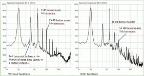
hidjedewitje, remember we are talking subwoofer here, where THD is quite high, MFB or not. If you look at the graph in post #137 you can see that -94db is more than good enough ....
Definitely sealed. MFB only works properly with sealed.
B.
How can you be so sure??
If you use a filter matching the predicted output of the driver around the resonance I think you could make it work for ported design.
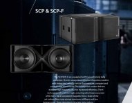
See picture and link
https://www.soundside.se/images/coda/pdf/CODA_-_Next_Generation_Brochure_SCREEN.pdf
Attachments
The ACE bass is not current drive. It uses current sensing to generate a complex, partly negative, output impedance for the driving amplifier. This quite simple and reliable technology was presented in 1978 and is still in use by ACE/AudioPro, Yamaha for its affordable bass loudspeakers, and PSI.One point which has not been discussed is the fact that all these solutions has only been applied to closed box designs. Only the ACE Bass (current drive) solution takes a vented design into consideration.
hidjedewitje, remember we are talking subwoofer here, where THD is quite high, MFB or not. If you look at the graph in post #137 you can see that -94db is more than good enough ....
While I agree that subs always have high distortion (regardless of MFB), I wouldn't make a statement like that. It's also true that we are much less sensitive in the bass area.
The part where I disagree is that because drivers are the dominant factor, we shouldn't pay attention to the quality of electronics. By your logic a amplifier and DAC with THD+n of -60dB would be enough, because the majority of drivers distort above that level.
I have never tried to discern DAC's at sub level only. Modern DAC's are quite good (only low frequency jitter can be a bit tricky), and most of them perform well below the quality of CD's. I doubt it's audible.
Though Grimm is a company that really strives to get the best possible. Apparently the tiny bit of phase shift is a lot more valuable than DAC distortion. To me it's very interisting how they optimise competely for latency instead of making a compromise.
If you look at ANC solutions:
DA7401 | Dialog Semiconductor
You gain about have about 25uS analog to analog delay and a lower Fs (384kHz) but you win about 20dB of THD+n.
These solutions would also sound very reasonable to me!
Must have been our shortest debate ever, Ben.... 😀OK, looks like we have a debate going on here.
Is Klippel system feedback or is it some kind of engineering fantasy that you can perfectly predict how a device will behave and thus can pre-correct it?
I'm betting on the second since it kind of fits the Klippel mind-set (and seems sadly naive to me).
B.
The other possibility would have been a built in analyzing function determining some parameters and use them to correct the signal afterwards.
You are right , my mistake ...The ACE bass is not current drive.
Still I find it a good example of how to lower THD, with all the output / efficiency benefits you have in a ported / PR system
Must have been our shortest debate ever, Ben.... 😀
The other possibility would have been a built in analyzing function determining some parameters and use them to correct the signal afterwards.
In that case, would you please tell us which approach Klippel is using: engineering fantasy using pre-correction or MFB or something else?
And I hope you will not use language that makes no sense like, "correct the signal afterwards". What could that mean?
B.
Last edited:
Ben, when did I claim to know their approach? Excuses for the inaccurate description... it doesn't make sense as you correctly noticed.In that case, would you please tell us which approach Klippel is using: engineering fantasy using pre-correction or MFB or something else?
And I hope you will not use language that makes no sense like, "correct the signal afterwards". What could that mean?
B.
I remember the old ads for LWE speakers Louis W. Erath (LWE-Acoustron) Lives! Still Building Speakers, Networks & Amps - 2-Channel Home Audio - The Klipsch Audio Community
a beat Karlson exhibited 10dB less sideband activity with two tones than a reflex the size of K15's rear chamber and similar system tuning - but I forgot to turn off a window AC when doing the Karlson 🙁
https://i.imgur.com/IFYiSFq.png
a beat Karlson exhibited 10dB less sideband activity with two tones than a reflex the size of K15's rear chamber and similar system tuning - but I forgot to turn off a window AC when doing the Karlson 🙁
https://i.imgur.com/IFYiSFq.png
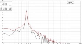
^^^^ Wow! That's really impressive!
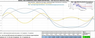
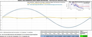
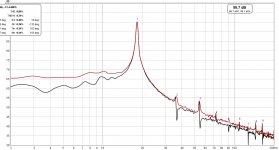
Taking THD from 41% down to 6.6% ! ! !
Here is how based on the distortion measurements listed above the cone movement would look like before and after servo correction
-
Taking THD from 41% down to 6.6% ! ! !
Here is how based on the distortion measurements listed above the cone movement would look like before and after servo correction
-
Attachments
Last edited:
On the other hand as somebody mentioned already if you start with a cleaner driver which is not driven past its limits you will not need servo correction as much.
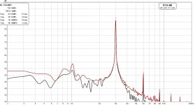
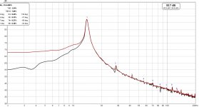
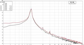
Below is my sealed sub with just regular $45 driver "Dayton Audio 8" DCS205-4".
Driven at 0.8 Xmax;
18Hz distortion measurements
THD = 1.4%
-
Below is my sealed sub with just regular $45 driver "Dayton Audio 8" DCS205-4".
Driven at 0.8 Xmax;
18Hz distortion measurements
THD = 1.4%
-
Attachments

Last edited:
Those figures for THD look like nothing I've ever seen before for any driver of any kind. Could it be due to testing at 18 Hz that is far outside the usual band for an 8-inch driver or other aspects of your test system?
B.
B.
@ Ben. I do not know what the latest Klippel approach is, but his earlier work, as applied, refined and extended by Hans Schurer in his PhD thesis at the University Twente is all about determining the so called non-linear woofer parameters (no, that is not a typo) by a Volterra Expansion. You can find the thesis on the internet I believe. Problem is that the technique does not lend itself to series production: each woofer has to be measured individually and then should the pre-emphasis/feedforward controller be programmed on the basis of these non linear parameters. Costly and very time consuming, so commercially simply not feasible. But it works well in a lab.
Those figures for THD look like nothing I've ever seen before for any driver of any kind. Could it be due to testing at 18 Hz that is far outside the usual band for an 8-inch driver or other aspects of your test system?
B.
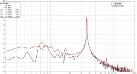
@Ben
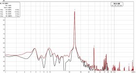
Here are my subwoofer full spectrum measurements - from 8Hz to 37Hz (xover is at 40Hz).
Measurements are done with REW and calibrated UMIK.
For 8Hz-37Hz range the THD is around 1%
Really clean sub...
-
Attachments

- Home
- Loudspeakers
- Subwoofers
- Servo controlled subwoofers - why arent they used more often