Francisdumas,
Wow that’s very slick. Thank you! I’ll link it from post 1.
Cheers,
X
Edit: Vladc- yours looks great too!
Wow that’s very slick. Thank you! I’ll link it from post 1.
Cheers,
X
Edit: Vladc- yours looks great too!
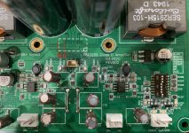
I have a silkscreen error to report. VladC caught this as he is the first one to attempt to build and got this far. It’s for C203/R203: they are swapped. The C should be an R and the R should be a C. For some reason, this escaped me as I may have assembled by visual symmetry. Then assembly house had a placement file so avoided it.
Thank you, VladC and so sorry for your time wasted to debug it. We all owe you a thanks!


Thank you, VladC and so sorry for your time wasted to debug it. We all owe you a thanks!
Attachments
15dB gain is 5.62x gain x 4.1vrms is 23.0 Vrms output. That’s good for 66w. Quite loud but not close to the typical max of 120w at 8ohms. You want 31.6 Vrms output to hit clipping.
So you need a preamp capable of 5.62 Vrms. That’s about 16Vpp.
The new SE/Bal to Bal preamp that I just tested will serve that purpose well and give you SE to balanced conversion.
If you replace the the PFFB 2k7 input resistors ( A, B, C, D) with a jumper (0R), your gain will be 22dB and 4.1vrms should be fine. THD increases about 6dB, but still very low.
Thanks for this info X, I have the Yarra with Melbourne’s waiting to be built so will use this amp with that preamp, if I can build it without hiccup.
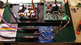
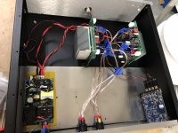
X - The parts arrived for the prototype SE/Bal board, so been busy getting that put together. Sorted out the XLR jack issue fine. Had a chance to test it this afternoon and it's singing beautifully! The combo with the 3255 is super quiet. That amp board turned out really nice and sounds great with the SMPS PSU. I haven't tested it in my main system yet, but I'm sure it will sound very nice.
So, my integration with the enclosure is coming along nicely now that I have all the sub-components. I need to finish the front and rear panel designs and get them sent off to FPExpress. Hopefully, I'll have more pictures to share in a couple weeks - after vacation.
So, my integration with the enclosure is coming along nicely now that I have all the sub-components. I need to finish the front and rear panel designs and get them sent off to FPExpress. Hopefully, I'll have more pictures to share in a couple weeks - after vacation.
Attachments
X - The parts arrived for the prototype SE/Bal board, so been busy getting that put together. Sorted out the XLR jack issue fine. Had a chance to test it this afternoon and it's singing beautifully! The combo with the 3255 is super quiet. That amp board turned out really nice and sounds great with the SMPS PSU. I haven't tested it in my main system yet, but I'm sure it will sound very nice.
So, my integration with the enclosure is coming along nicely now that I have all the sub-components. I need to finish the front and rear panel designs and get them sent off to FPExpress. Hopefully, I'll have more pictures to share in a couple weeks - after vacation.
Did I miss a group buy for this board?
tommost
Hi Tom,
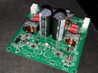
No - Redjr expressed to me that he was in a hurry and willing to accept the pre-production prototype PCB and serve as a beta tester. The production one has not been formally released yet and hadMs the extra feature of simultaneous SE outputs in addition to Bal outputs. This is useful as a pass through with gain to drive a subwoofer or other device. The new production version will have a gain of 0dB/12dB/20dB. I just got the production verification PCBs delivered by DHL a few minutes ago. Please stand by - will post GB soon.
It’s going to be called the BTSB (Best Thing since Sliced Bread) Buffer. Uses state of the art OPA1656 opamps, LME9472 balanced line drivers, on-board Murata isolated DC-DC converter for low noise +/-15v power.
@Redjr:
That looks great! Glad it is singing away. So this is a second smaller box you are making then? The first one had the Sparkfun THAT1646 SE/Bal converters I believe.
Is that a Connexelectronic SMPS?
Last edited:
Those are the input and output audio signal coupling caps. Nominally, 10uF 35v Elna Silmic II’s. They can be replaced by film caps, and indeed there is space for film caps there (but not MKP - too big). The Elna Silmic II’s are probably the best sounding compact 10uF caps around even though they are electrolytic. Caps here are not optional, since the front end NE5532 opamps operate from a single rail supply of 12v and the output and feedback on the input sit at about 6v using a voltage divider. This was part of the TI factory design and is an effort on keeping system simpler and not requiring a dual rail DC-DC converter.
Someone has asked the right way to attach a single ended signal such as coming from an RCA to a balanced input buffer. The buffer itself adheres to the XLR convention which is pin 2 to +xe in, pin 3 to -xe in, and pin 1 to chassis. If you are connecting a single ended signal the signal + connects to pin 2, and the signal - connects to pin 3. It is highly recommended that signal - be isolated from chassis.
For those of you that are using two wire plus shield cabling with an RCA at the source end do it per Neurochrome's recommendation, which is to connect the RCA center pin to the wire comprising +xe and the RCA outside to both -xe and shield at the source end. At the buffer input connect the +xe wire to pin 2, the -xe wire to pin 3 and the shield to pin 1.
For those of you that are using two wire plus shield cabling with an RCA at the source end do it per Neurochrome's recommendation, which is to connect the RCA center pin to the wire comprising +xe and the RCA outside to both -xe and shield at the source end. At the buffer input connect the +xe wire to pin 2, the -xe wire to pin 3 and the shield to pin 1.
So in essence, by tying -xe and the shield at the source, and then tying the shield to pin 1 at the buffer, you are effectively grounding -xe aren't you? That's the only way I've been able to get the RCAs to work. I just strapped pin 1 and 3 at the MolexKK connector. Left in that configuration w/o any RCA, I then plugged back in Balanced XLRs and everything still seemed to work and sounded fine - on my bench. But I'm somewhat leary that pin 3 (-xe) being grounded, is still influencing the 'balanced' circuitry sonically - although I cannot hear any subtle difference. But I will admit, I don't fully understand how the circuit is working. 🙁Someone has asked the right way to attach a single ended signal such as coming from an RCA to a balanced input buffer. The buffer itself adheres to the XLR convention which is pin 2 to +xe in, pin 3 to -xe in, and pin 1 to chassis. If you are connecting a single ended signal the signal + connects to pin 2, and the signal - connects to pin 3.This did not work. It is highly recommended that signal - be isolated from chassis.
For those of you that are using two wire plus shield cabling with an RCA at the source end do it per Neurochrome's recommendation, which is to connect the RCA center pin to the wire comprising +xe and the RCA outside to both -xe and shield at the source end. At the buffer input connect the +xe wire to pin 2, the -xe wire to pin 3 and the shield to pin 1.
@redjr,
The balanced amp input does just that. It buffers and amplifies the difference between +in and -in. If -in happens to be 0V, that is fine. Note that if you intentionally want the buffer to be inverting the hot signal can connect to -in and the other side, 0V in this case, to +in.
To answer your question, yes you are tying -in to ground with the RCA as you describe.
the somewhat subtle difference of tying -in and shield at the source end is that whatever interfering signal gets picked up by that shield goes to chassis and not added to the intended signal in.
@redjr,
The balanced amp input does just that. It buffers and amplifies the difference between +in and -in. If -in happens to be 0V, that is fine. Note that if you intentionally want the buffer to be inverting the hot signal can connect to -in and the other side, 0V in this case, to +in.
To answer your question, yes you are tying -in to ground with the RCA as you describe.
the somewhat subtle difference of tying -in and shield at the source end is that whatever interfering signal gets picked up by that shield goes to chassis and not added to the intended signal in.
Very good. That explains it better. My configuration, as is, will work as I intend to use it.
Nice work Nrabbit! Not bad for hand soldering. Have you checked to see if you get 12v and 3.3v yet?
Not yet. Although I managed to get the TPA3255 installed, nothing else is on the bottom side yet as I killed my soldering iron. Got a nice new hakko on the way.
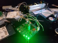
Finished my amp today.
Running LXMinis, sounds great. The way it configured now (SE inputs, 2V max from MiniDSP), power limited at ~15W RMS per channel. Which is less then these drivers are capable of but still insanely loud. Going to settle with this config for now. Need to optimize power supply, TPA3255s generate surprisingly large amounts of heat just idling at 48v.
Running LXMinis, sounds great. The way it configured now (SE inputs, 2V max from MiniDSP), power limited at ~15W RMS per channel. Which is less then these drivers are capable of but still insanely loud. Going to settle with this config for now. Need to optimize power supply, TPA3255s generate surprisingly large amounts of heat just idling at 48v.
Attachments
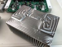
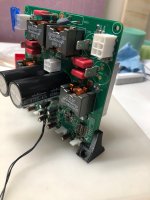
Nice work Vlad! You did a superb job on that CNC’d custom heatsink! I like the 3D printed brackets to hold then board vertically. At the powers you run, no need to orient them up for natural convection. You are the first to run it SE on the input.
That looks great - looks all built to me what part are you waiting for? I never measured idle consumption yet but 7w sounds about right. It’s warm even when idle.
- Home
- Group Buys
- TPA3255 Reference Design Class D Amp GB