Hi Guys,
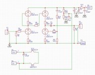
I have a query regarding the voltage rating for the output coupling caps for an aikido preamp.
I am not yet knowledgeable enough to figure out what voltage would be present at the output.

It looks to me like there would not be a large DC voltage present between the top grid and the bottom plate of v2 since the bottom plate is not exposed to the B+.
Based on this assumption it looks to me like a 250v k42y-10 cap would be safe for use here.
Am I dumb and/or wrong here?
I have a query regarding the voltage rating for the output coupling caps for an aikido preamp.
I am not yet knowledgeable enough to figure out what voltage would be present at the output.

It looks to me like there would not be a large DC voltage present between the top grid and the bottom plate of v2 since the bottom plate is not exposed to the B+.
Based on this assumption it looks to me like a 250v k42y-10 cap would be safe for use here.
Am I dumb and/or wrong here?
I would say that you have to consider all angles such as the warm up phase and possible fault conditions. Just looking at the normal steady state conditions may not be realistic.
Ideally you need the cap to be equal to the B+ voltage to cover all those scenarios.
Ideally you need the cap to be equal to the B+ voltage to cover all those scenarios.
When the amp is up and running, the voltage across C3 (if it's the cap you're interested in) will be about 0.5B+.
But during the power-on and/or power-off this voltage might theoretically reach full B+ if V2 halves are not perfectly identical (and they never are).
So the voltage rating should be "at least B+" to be 100% safe.
But during the power-on and/or power-off this voltage might theoretically reach full B+ if V2 halves are not perfectly identical (and they never are).
So the voltage rating should be "at least B+" to be 100% safe.
Also, check what the maximum B+ voltage is before all the tubes warm up.
Want to be safe for all possible situations, rate the capacitor as high as the unloaded B+.
Suppose the bottom half of the 6SN7, V2.1 goes open, the cap will go to B+.
Want to be safe for all possible situations, rate the capacitor as high as the unloaded B+.
Suppose the bottom half of the 6SN7, V2.1 goes open, the cap will go to B+.
B+ will be regulated 265v before R12.
250v at the plates after R12.
So in theory a 250v rated cap should be ok?
I can't find a proper spec sheet for the k42-y to see what the surge rating is.
I would normally go the next voltage rating up for safety but that isn't really an issue here.
250v at the plates after R12.
So in theory a 250v rated cap should be ok?
I can't find a proper spec sheet for the k42-y to see what the surge rating is.
I would normally go the next voltage rating up for safety but that isn't really an issue here.
Well it's your risk! Regulated voltage supplies can fail just like anything else. As others have said, an unloaded B+ plus a margin, thus 265V MINIMUM plus margin is prudent, just change the capacitor type. K42-Y are good value but not an essential component choice in this (to my mind).
I'd opt for 350V just because I sometimes fiddle with things and like a safety net. If you don't like the amp for whatever reason then the caps can be salvaged so it's not money wasted.
I'd opt for 350V just because I sometimes fiddle with things and like a safety net. If you don't like the amp for whatever reason then the caps can be salvaged so it's not money wasted.
250V is fine in this case. Modern caps handle 20% overvoltage (some more). If they sit at above rating for extended periods the life expectancy will be lower but short periods are no prob.
I don’t think it is a good policy to not have some over design in a tube amp, to minimize collateral damage in failure cases. We are talking DIY with 60 year old components, in many cases.
Sadface,
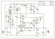
Your schematic, post # 1, did not show a regulator.
Give a partial schematic, and get a partially wrong answer.
We can not assume all that you know about your amplifier, but did not tell us in post # 1.
Depending on the regulator circuit, it may, or may not, have a transient voltage that is higher than the final regulated voltage.
Assumptions are just that, assumptions.
rule of thumb, consider the B+, if say 300vdc, then 400vdc rated coupling caps....but nothing stops you from using 630vdc rated caps..
Pass DIY Addict
Joined 2000
Paid Member
I'm a relative tube noob as well, but it is clear that you want a coupling cap that is rated higher than your B+ voltage. Hard to go wrong with a 600v rated cap. Always plan/build for a worst case scenario. If you are using NOS Russian PIO caps, you need to test them to make sure they don't leak any DC voltage. If you build a leak detector (see attached PDF), you should not be able to measure ANY voltage on the meter. Not even one micro volt.
Attachments
Last edited:
Well it's your risk! Regulated voltage supplies can fail just like anything else. As others have said, an unloaded B+ plus a margin, thus 265V MINIMUM plus margin is prudent, just change the capacitor type. K42-Y are good value but not an essential component choice in this (to my mind).
I'd opt for 350V just because I sometimes fiddle with things and like a safety net. If you don't like the amp for whatever reason then the caps can be salvaged so it's not money wasted.
Thanks, I had not considered that angle.
Sadface,
Your schematic, post # 1, did not show a regulator.
Give a partial schematic, and get a partially wrong answer.
We can not assume all that you know about your amplifier, but did not tell us in post # 1.
Depending on the regulator circuit, it may, or may not, have a transient voltage that is higher than the final regulated voltage.
Assumptions are just that, assumptions.
Thank you, point taken regarding half information and assumptions.
rule of thumb, consider the B+, if say 300vdc, then 400vdc rated coupling caps....but nothing stops you from using 630vdc rated caps..
That would be my normal approach but I was trying to get away with using a pair K42-y caps that I have on hand.
I'm a relative tube noob as well, but it is clear that you want a coupling cap that is rated higher than your B+ voltage. Hard to go wrong with a 600v rated cap. Always plan/build for a worst case scenario. If you are using NOS Russian PIO caps, you need to test them to make sure they don't leak any DC voltage. If you build a leak detector (see attached PDF), you should not be able to measure ANY voltage on the meter. Not even one micro volt.
Thanks for that pdf.
The regulator in question is Jan's Treg.
The power transformer will be 230vac, giving something like 320vdc at the filter caps (minus losses).

To throw a spanner in the discussion, John Broskie specifies a 250Vdc rated cap for this position in the Octal Stereo Manual.
Does this change opinions at all?
The power transformer will be 230vac, giving something like 320vdc at the filter caps (minus losses).

To throw a spanner in the discussion, John Broskie specifies a 250Vdc rated cap for this position in the Octal Stereo Manual.
Does this change opinions at all?
Considering that his current kit has 1kV CDE caps - not really.To throw a spanner in the discussion, John Broskie specifies a 250Vdc rated cap for this position in the Octal Stereo Manual.
Does this change opinions at all?
And mind you, those K42-Ys have the nominal shelf life of 10 years, but in practice they might be dead much sooner. If they're 20+ years old, I wouldn't even bothered to test them - there's 99% chance they're garbage.
Of course, all that shouldn't stop you from trying 😎
Also, check what the maximum B+ voltage is before all the tubes warm up.
Want to be safe for all possible situations, rate the capacitor as high as the unloaded B+.
Suppose the bottom half of the 6SN7, V2.1 goes open, the cap will go to B+.
If V2.1 goes open, no DC current will flow through V2.3 and the cap will see 0V. I did this exact thing last week when I forgot to ground the cathode resistor. Now if V2.1 goes short, then the cap will see B+ I guess, but when was the last time you saw a dual triode go short?
Even with typical mismatch in warmup, I've never seen the cap with more than 2/3 B+ across it. The one I just built I used 200V caps, the B+ unloaded being 280V, 250V loaded, the voltage at the cap being 125V briefly hitting 160V, then dipping to 90V on startup.
Agrees it's good practice to use a voltage = B+, but sometimes you can't. 400V MKP 10uF caps are gigantic, for instance 🙂 C4GAFUD5100AA1J KEMET | Mouser Canada
Last edited:
Just get some good WIMA 630V and you'll never have to worry. The price difference between some 250 volt cap which might destroy your amp and something which will always be safe is about the price of a cup of coffee... A no-brainer if you ask me.
Yup, that's the beauty of DIY though. That price of the cup of coffee would add up to a lot of money if you were mass producing them, and and some companies tend to prioritize profit over quality.
Yes, but 400V 1uf caps aren't 🙂400V MKP 10uF caps are gigantic, for instance 🙂
Audiophiler caps (like $3/pair including worldwide shipping) are quite decent.
Thanks guys.
Prudence wins.
I will just stick with the 630v CDE 942 series as was originally the plan.
Prudence wins.
I will just stick with the 630v CDE 942 series as was originally the plan.
- Home
- Amplifiers
- Tubes / Valves
- Coupling cap voltage rating