The regulator in question is Jan's Treg.
The power transformer will be 230vac, giving something like 320vdc at the filter caps (minus losses).
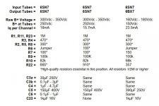
View attachment 854908
To throw a spanner in the discussion, John Broskie specifies a 250Vdc rated cap for this position in the Octal Stereo Manual.
Does this change opinions at all?
i think the question you have to ask yourself is, what if tubes or devices fail,what will the cap see in terms of dc volts?
deciding then becomes easy..
Thanks guys.
Prudence wins.
I will just stick with the 630v CDE 942 series as was originally the plan.
Probably the safest way to go. Caps don't cost that much and are cheap insurance against loosing costly tubes.
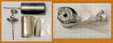
Ok I have used K42y russion 25ov PIO a good bit, and I do have a few comments, they are paper, not film so they will take 20% over voltage or so, no more.
As one poster mentioned, they must be checked for leakage, I have had one leak....and here is the drum roll, I had a failure I did not understand, desoldered the K42y, and it was leaky after, when I had tested it as good, before installation....The problem:
The K42y was installed in 4way junction that I had to get really hot for my silver solder to wet nicely.
I believe I damaged the K42y during soldering.....so this is another tricky issue when you are close to overvoltage ....this kind of damage will take anything "extra"....
I heat sink them when I solder now....
Also I am not sure which capacitors you are referring to in your schematic...All of them? C3, C4, C5, C6...etc...
And for each capacitor a fault analysis question should be asked specifically if you are going to go ahead....i.e. if this capacitor fails as a short what will the results be, for each capacitor position.
I like Parts Express Polyprop and Foil a lot also, and their 250v will be fine, for cheap and really excellent sound....please make sure you do use a foil capacitor for the sound,....these Parts Express polyFoil 250v will do 400v all day long....as I have them doing in my Harmon Kardon A300 restorations B+ bypass...
Thanks and Good Luck,
Sincerely,
-18db
What is C6 for? That looks like a misteak(sic) to me.
On board psu decoupling for the heaters.
I’m open to the idea that it is unnecessary however it seems to be present on all of Broskie’s designs from which this is adapted.
Are you sure? I see in the manual:To throw a spanner in the discussion, John Broskie specifies a 250Vdc rated cap for this position in the Octal Stereo Manual.
Does this change opinions at all?
"*voltage rating must equal or exceed B+ voltage"
https://www.audiofaidate.org/uploaded/lord_orione/Octal_Aikido_PCB.pdf
Are you sure? I see in the manual:
"*voltage rating must equal or exceed B+ voltage"
https://www.audiofaidate.org/uploaded/lord_orione/Octal_Aikido_PCB.pdf
I'm working off a newer version from 2013.

Last edited:
Slightly off topic relative the the thread title but now I am onto sizing the capacitor in terms of uF.
I will be using the CDE 942c series 600v caps.
1uF would be my default value however I am considering the 2.5uF that is also in stock at Mouser.
By my calculation: The combined impedance of the 1M resistor at the output and the 25k input impedance of the next stage gives 24k impedance in parallel with the output coupling cap.
According to (Sample)RC Low-pass Filter Design Tool - Result -
A 1uF cap gives about -0.45dB @ 20Hz. -0.29dB @ 25Hz
A 2.5uF cap gives about -0.09dB @ 20 Hz. -0.06dB @ 25Hz.
For the doubled cost of the larger value capacitor. Am I likely to notice any difference in bass response?
I'm working off a newer version from 2013.
View attachment 855768
Ah. IIRC in later versions of the design he added 1M 'emergency' resistors to the grid of the top output tube, so even if one is pulled, the output capacitor won't see more than 250V.
Slightly off topic relative the the thread title but now I am onto sizing the capacitor in terms of uF.
I will be using the CDE 942c series 600v caps.
1uF would be my default value however I am considering the 2.5uF that is also in stock at Mouser.
By my calculation: The combined impedance of the 1M resistor at the output and the 25k input impedance of the next stage gives 24k impedance in parallel with the output coupling cap.
According to (Sample)RC Low-pass Filter Design Tool - Result -
A 1uF cap gives about -0.45dB @ 20Hz. -0.29dB @ 25Hz
A 2.5uF cap gives about -0.09dB @ 20 Hz. -0.06dB @ 25Hz.
For the doubled cost of the larger value capacitor. Am I likely to notice any difference in bass response?
I'd do it. I'd probably even go to 3.3uF.
Also you might want to check out the Kemet C4G series. C4GAHUD4330AA1J KEMET | Mouser Canada
I use them in (10uF) in my current integrated amp for the preamp out. I'm also going to use them for the output caps (2x30uF in parallel) for an Aikidoesque 470R HP amp one day 🙂
Last edited:
- Home
- Amplifiers
- Tubes / Valves
- Coupling cap voltage rating
