Common emitter works too - and with that you don’t need an op amp that can drive 100 ohm loads (5532 is often used to drive common base level shifter).
Opamp provides sufficient open loop gain , what is required is fastest possible VAS, as the dominant pole is in the op amp. I would prefer a 10-20khz pole op amp as AD826 but it is not jfet .
1K is just symbolic .
Ok.
Opamp provides sufficient open loop gain , what is required is fastest possible VAS, as the dominant pole is in the op amp.
Again, instead. It'll be better to use uncompensated opamp since Hi-Z point on the crystal anyway smaller and less parasitic than on an external PCB in terms of leaks and capacitance. So from the opamp we can pick a way more gain than externally.
If you need something hi-gain and JFET-input - try AD8067.
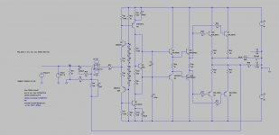
For your entertainment, a version with the common base level shifter. Looks better than I expected, quite honestly. Distortion is improved slightly over the previous version at the cost of 2 extra small-signal transistors. The schematic is unchanged enough that it should be easy to add an extra footprint in the PCB to allow for the other version with the capacitors, which could make for an interesting real-world comparison.
Two 100 pF capacitors, C1 and C2, were added as it seems to help the phase margin. It now has 50 degrees of phase margin as opposed to 35 degrees of phase margin- an improvement.
As can be seen in the image monitoring the current through R27, it shouldn't require too much from the op-amp to drive it. I calculated an input impedance (as seen by the op-amp) of roughly 500 ohms. While not low, even a TL071 should have no difficulties driving this, since it doesn't have to swing much voltage.
When I have time, I'll play with a common emitter version and see how it compares.
Attachments
Hi H713, can you post a small step response (+/- 100mV) for the circuit on post #23? I am curious how stable the connection is.
Best, SandroHV
Best, SandroHV
Burning a lot of current in that 5k bias resistor, too. Tie them to your +/-15 instead of the main supply rail.
Actually you can just connect the bases of the common-base transistors to the 15V rails directly, even simpler.
If you do that you need to increase the emitter resistor value or you’ll burn 14mA in the level shifter transistors. Then you start losing gain without adding any linearizing local feedback. Pick your poison. Mine would be the diodes.
The string of diodes and 5K to the main rails was more of a "quick-and-dirty" simulation. I would probably use LEDs and the op-amp power rails in a practical design.
If you do that you need to increase the emitter resistor value or you’ll burn 14mA in the level shifter transistors. Then you start losing gain without adding any linearizing local feedback. Pick your poison. Mine would be the diodes.
Then power the opamps from +/-5V and use rail-to-rail ones.
Then power the opamps from +/-5V and use rail-to-rail ones.
What is the advantage of doing this over two LEDs?
Hi H713, can you post a small step response (+/- 100mV) for the circuit on post #23? I am curious how stable the connection is.
Best, SandroHV
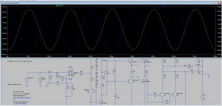
This what you wanted? Input is +/- 100mV.
Attachments
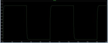
I would have thought given that the collector of Q1 and Q8 is a HiZ node, phase margin would have been degraded and given overshoot. But I guess not.
What is the advantage of doing this over two LEDs?
Fewer parts, prevents the opamp from being able to reverse-bias base-emitter junctions of the common-base transistors too (most transistors fail if reverse base-emitter voltage gets more than a few volts).
With the common emitter version, I’ve never found reverse breakdown to be an actual problem. It runs beyond Vbeo rating, but that can be “almost” fixed by using the C1008/A708 pair, rated at 8V. They don’t break down till much higher - I use them for audio signal clamps because of the vbeo rating and the low on resistance. Cascode with a high voltage type on big rail voltage.
Another improvement is to clamp the op amp output with 5.1V BTB zeners with 1k to limit the op amp current. Detecting current thru that branch is a perfect way of detecting clipping to activate a soft clip or compressor circuit. Of course there is always the option of 5V op amp rails - but that limits what you can do with the supply - on real world implementations there is often a myriad of protection and support circuitry operating off those supplies. When you start adding all THOSE components, a bit extra complexity or BOM cost is lost in the noise.
Another improvement is to clamp the op amp output with 5.1V BTB zeners with 1k to limit the op amp current. Detecting current thru that branch is a perfect way of detecting clipping to activate a soft clip or compressor circuit. Of course there is always the option of 5V op amp rails - but that limits what you can do with the supply - on real world implementations there is often a myriad of protection and support circuitry operating off those supplies. When you start adding all THOSE components, a bit extra complexity or BOM cost is lost in the noise.
Usually, the output push-pull cascade of an op-amp is transferred in SE to a pure class A, as for example in this diagram p10. NAD S100 - Manual - Stereo Preamplifier - HiFi Engine
The inputs of the op-amp are ok ?
In what regard? They are not switched, even though the feedback goes to the non-inverting input. This is because the VAS is inverting.
With the common emitter version, I’ve never found reverse breakdown to be an actual problem. It runs beyond Vbeo rating, but that can be “almost” fixed by using the C1008/A708 pair, rated at 8V. They don’t break down till much higher - I use them for audio signal clamps because of the vbeo rating and the low on resistance. Cascode with a high voltage type on big rail voltage.
Another improvement is to clamp the op amp output with 5.1V BTB zeners with 1k to limit the op amp current. Detecting current thru that branch is a perfect way of detecting clipping to activate a soft clip or compressor circuit. Of course there is always the option of 5V op amp rails - but that limits what you can do with the supply - on real world implementations there is often a myriad of protection and support circuitry operating off those supplies. When you start adding all THOSE components, a bit extra complexity or BOM cost is lost in the noise.
At least from the simulations I've done, under no conditions would the base-emitter junction in the level shifting transistors be reverse-biased. The output of the op-amp is incredibly small.
- Home
- Amplifiers
- Solid State
- Op-Amp Input Stage Design