Op amp output will spike to 13V when the amp clips. I’ve seen it on the scope - and I drive my amps to clipping all the time. Well not ALL the tine, but it is considered normal use. 8 or so volts reverse bias caused by this doesn’t seem to hurt anything - at least with the transistors I’ve used. If you hold out for a particularly low noise type, you might not get away with as much -Vbe. The less degeneration you use in the stage (ie, less drop in emitter or base circuit), the closer to -13v you will get on the vbe during clip. At some point they do break down. But if you absolutely never clip your amp you will never see this.
I'm inclined to think that a resistor in series with the output of the op-amp and a few 1N4148s could stop this from ever becoming an issue. Then I can keep the +/- 15V supply, and wouldn't have to have a +/- 5V supply that wouldn't be used for anything else.
8V reverse bias on a base-emitter junction may increase the transistor noise if it doesn't blow the device. Base-emitter avalanche breakdown dumps energy into the base region, rather than the collector (which is designed to handle dissipation).
The fact its avalanche breakdown is probably related to the damage mechanism that increases noise, and due to the heavy doping levels the electric field strength in a reverse-biased base-emitter junction is extremely high, much more than the base-collector junction (high doping levels make for very narrow depletion zone).
See page 32 of this: https://www.uio.no/studier/emner/matnat/ifi/INF5460/h16/undervisningsmateriale/f8-1p.pdf
Mark is correct. Also 8V is not a hard rule, it is very transistor dependent. Fast transistors start exhibiting damage at reverse VBE voltages of as low as 2V.
Two damage symtoms:
- Reduced beta
- Increased 1/f noise
The fix is not complicated though, H713 already mentioned it in #42. A reverse bias clamp diode and a current limiting resistor.
Two damage symtoms:
- Reduced beta
- Increased 1/f noise
The fix is not complicated though, H713 already mentioned it in #42. A reverse bias clamp diode and a current limiting resistor.
Sorry for the delay in this project. Work got busy for a while, and then I bought a whole bunch of equipment at auction (because I really, really need more boat anchors, right?)
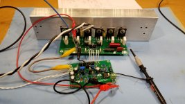
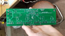
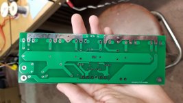
For this project I decided to try separating the output stage from the rest of the power amp. I'd say it was for "grounding reasons", but in reality it was to simplify the process of testing new input / VAS stages without having to deal with the output stage every time. This saves cost and time.
Distortion looks fine, probably limited by my measurement setup and test configuration, but even into a 4 ohm load it never got worse than .007%. That is using an OPA604 and some spaghetti grounding. Stability isn't great, see attached images. After tweaking a few cap values, I was able to get it considerably better. I also added the compensation cap to the new PCB layout that will hopefully allow a 5534 to work in this circuit without making everything go ballistic. Other suggestions for through-hole single op-amps are welcome.
Since the shipping from china usually costs more than the PCBs themselves, I also ordered output boards that use TO-220 MOSFETs. I know the SOA of the TO-247 FETs is much better, but the FET version will be used with around +/- 35V rails anyways.
Quick question for those who play with FETs on a regular basis: Just how different is the DC SOA for the IRF540N compared to the IRF540? I know it's a smaller die, but I'd be interested to hear whether it's a game-changer or not since the 540N is less expensive. Also, would I be smart to just use IRF640/640N FETs instead? At least if the IR application note has anything to say, the higher voltage parts with a higher Rdson handle linear operation significantly better.
Attachments
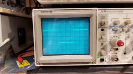
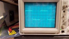
The square wave response of the amplifier in the second pic looks quite stable, the 5534 is a good opamp but remember to add at least 22pF of compensation if using gains lower than 3, if you add feedback resistors (not using it as a buffer) you will definitely need to add some pF's across it to improve stability, if you can afford it, the AD797 is loved by many in case noise is an issue, apparently THD is also lower than the 5534, but I don't know what your source impedance is or what you plan to connect to it.
I thought about the AD797, but the big advantage that it holds (extremely low noise) is really not a big deal here. THD is improved over the 5534, but IMO not enough to justify an almost ten fold increase in cost. I really wish TI would release a single version of the LM4562, but alas, I don't think that will happen.
This amplifier will probably be driven by another 5534. I'm presently working on the differential input circuit, which will use 3 sections of a TL074 (actually an AD713 in this case, but only because I have them in stock) as an instrumentation amplifier. An AD5450 and a 5534 (or an OPA604) are used to form a programmable gain amplifier that will be used for level controls. The 4th section of the TL074 is used as a buffer in case a regular pot is to be used for gain control- something like a 5K log can be used to keep noise down. Once I have that plus the digital control system to oversee everything, I'll post the details. I've seen the concept work on commercially built amplifiers, and it's really a nice solution. Used standalone with a Jensen transformer for differential outputs, it would make a really nice preamp.
This amplifier will probably be driven by another 5534. I'm presently working on the differential input circuit, which will use 3 sections of a TL074 (actually an AD713 in this case, but only because I have them in stock) as an instrumentation amplifier. An AD5450 and a 5534 (or an OPA604) are used to form a programmable gain amplifier that will be used for level controls. The 4th section of the TL074 is used as a buffer in case a regular pot is to be used for gain control- something like a 5K log can be used to keep noise down. Once I have that plus the digital control system to oversee everything, I'll post the details. I've seen the concept work on commercially built amplifiers, and it's really a nice solution. Used standalone with a Jensen transformer for differential outputs, it would make a really nice preamp.
The single version of the LM4562 used to be the LME49710, which was a National part, but got discontinued by TI some years ago. I really liked that chip because it was, in most cases, a drop-in replacement for the 5534. You can still find it on eBay but its authenticity is to be questioned.
If you want balanced inputs is better to use a THAT 1246 line reciever, Jensen transformers are great, but better still is no transformer to color the sound. They do provide excellent CMRR and EMI rejection thou.
If you want balanced inputs is better to use a THAT 1246 line reciever, Jensen transformers are great, but better still is no transformer to color the sound. They do provide excellent CMRR and EMI rejection thou.
Actually, the Jensen transformers were for an entirely different project and were going to be used as outputs specifically for their galvanic isolation.
- Home
- Amplifiers
- Solid State
- Op-Amp Input Stage Design