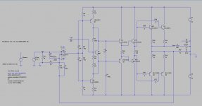
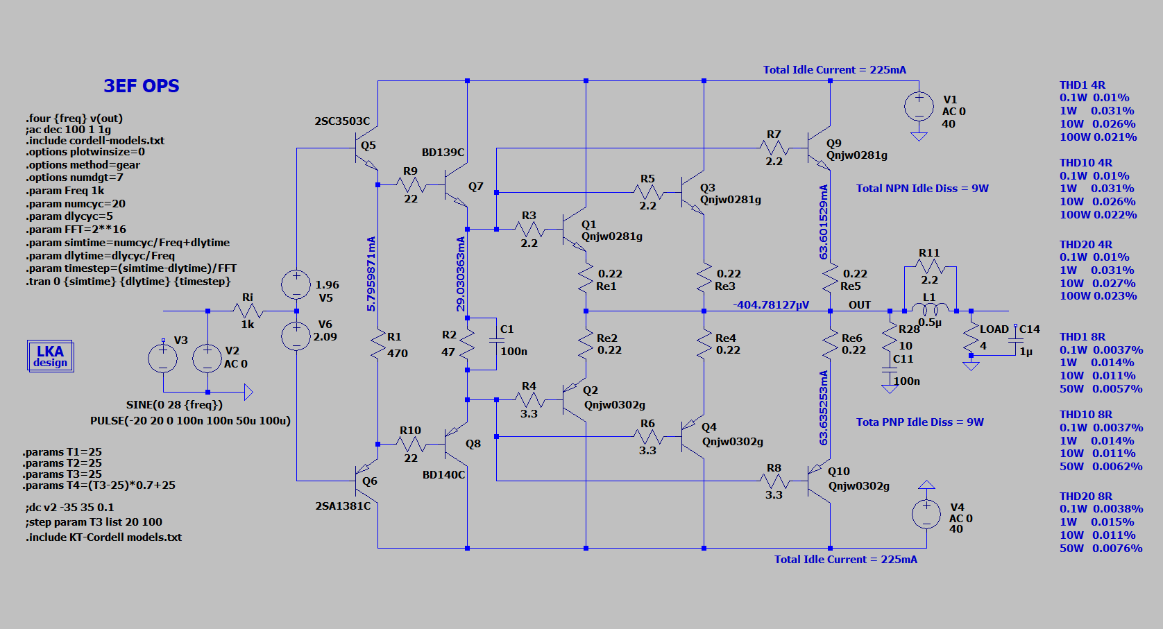
For my next project, I decided that I want to eliminate the need for a closely matched input pair by using a FET input op-amp instead. I figure it will be an interesting thing to experiment with.
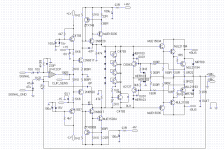
It's far from a new idea- the amp that my design is based off of is the Crest 1001A- which dates back to the 1980s. The schematics for the Crest are attached for reference. Adding a triple EF output stage seems to drastically reduce distortion (at least in simulation).
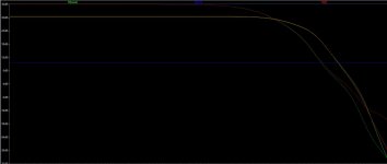
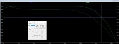
The design attached simulates quite well, with a few issues that need to be addressed going forward. First is stability- 36 degrees of phase margin seems a little borderline to me. From what I can see, the phase shift is occurring before the output stage.
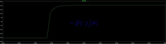
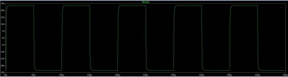
The 10K square wave simulation looks good, and shows a slew rate of about 85 V/us, which is plenty.
I still need to work out the details of VI limiting on this design, but its implementation shouldn't be much different from any other amp.
I'd love to hear suggestions regarding improvements to this design, particularly from those who have played with this topology before. I'd certainly like to get a bit more of a phase margin if I can, and I'm certainly not opposed to improving distortion.
It's far from a new idea- the amp that my design is based off of is the Crest 1001A- which dates back to the 1980s. The schematics for the Crest are attached for reference. Adding a triple EF output stage seems to drastically reduce distortion (at least in simulation).
The design attached simulates quite well, with a few issues that need to be addressed going forward. First is stability- 36 degrees of phase margin seems a little borderline to me. From what I can see, the phase shift is occurring before the output stage.
The 10K square wave simulation looks good, and shows a slew rate of about 85 V/us, which is plenty.
I still need to work out the details of VI limiting on this design, but its implementation shouldn't be much different from any other amp.
I'd love to hear suggestions regarding improvements to this design, particularly from those who have played with this topology before. I'd certainly like to get a bit more of a phase margin if I can, and I'm certainly not opposed to improving distortion.
Attachments
Your outputs are obsolete transistors, The far better ones proposed by LKA are MJL0281/0302.seehis circuit
drivers are 2sc4793/2sa1832.
You can get rid of C2,C4 capacitor linking by a complimentary common bases.
drivers are 2sc4793/2sa1832.
You can get rid of C2,C4 capacitor linking by a complimentary common bases.
Are you planning on using the AD711 or is it a place holder? There are better choices out there, the AD711 is old. Look at the ADA4622 for example.
Best, Sandro
@Kokoriantz, do you have an .asc for LKA's design?
Best, Sandro
@Kokoriantz, do you have an .asc for LKA's design?
My immediate suggestion is to add some rail ripple to you simulation - each rail at a different frequency and different to the signal. You'll see that C2 and C4 are coupling this straight into the signal path, and the differential mode will modulate the bias point.I'd love to hear suggestions regarding improvements to this design, particularly from those who have played with this topology before. I'd certainly like to get a bit more of a phase margin if I can, and I'm certainly not opposed to improving distortion.
One observation I'd make is to ensure whenever a signal changes its reference point from ground to a rail or back again, either provide very good decoupling on that section of the rail, or ensure the signal is in current-mode at the cross over.
Also the feedback take-off point should be just before the inductor, even though this won't matter for simulation (unless you
represent the wiring resistance explicitly). With real wires in the configuration shown there is a half-cycle IR signal generated between the NPN and PNP output devices, which will be seen by the feedback path and raise the baseline distortion.
[ you might want to contrast with one of my approachs: https://www.diyaudio.com/forums/solid-state/354131-novel-os-topology.html#post6196023 where the signal is passed as a current to the output devices - there are many other ways to do this of course ]
Last edited:
Are you planning on using the AD711 or is it a place holder? There are better choices out there, the AD711 is old. Look at the ADA4622 for example.
Best, Sandro
@Kokoriantz, do you have an .asc for LKA's design?
No, He didn't post.
My immediate suggestion is to add some rail ripple to you simulation - each rail at a different frequency and different to the signal. You'll see that C2 and C4 are coupling this straight into the signal path, and the differential mode will modulate the bias point.
The old BGWs with the LM318 in the front end got away with this - with the only ill effect being the 20uF electrolytics employed would eventually go bad. I personally don’t like the idea of the start up surge they create. Another variant employs a highly degenerated level shifter stage between the op amp and VAS, biased off the regulated op amp rails This eliminates both issues. Common emitter and common base versions have been used successfully. The circuit became a standard PA amp topology used by many - with distortion limited more by implementation and layout than the circuit or components used.
The only real problem with output triples is thermal tracking. You will never get the bias as stable and track the dynamic temp fluctuations as well as an EF2. There will be more lag. Higher initial bias helps this in hi-if applications as it has room to drift down, and up is not an issue unless it continues to run away. In PA use let it drift down, the music is loud enough anyway. These circuits can be made stable, regardless of stability related prejudices against triples. The best way to insure that is to take the lead compensation from the VAS output instead of the output stage. This gives even more phase lead In the HF feedback since it skips the phase shift thru the output stage.
Another thing that can be done with these amps is to (SACRILEGE !!!) degenerate the VAS. That’s right, put a load to ground off the collectors. This doesn’t increase distortion as much as one would expect. Stabilization is easier, early voltage differences in each side of the VAS matter less, and Linearizes the hell out of the output stage which lets you use outputs with less linear hFE vs Ic (like MJ15024’s). Having Way More Current Gain Than Needed means the combined hFE is almost immaterial. Taking the lead comp from this point also has a similar linearizing effect on the OUPUT stage.
Obsolete?
MJL3281AG is still availible.
MJL3281AG ON Semiconductor | Mouser
MJL1302AG is still availible.
MJL1302AG ON Semiconductor | Mouser
MJL3281AG is still availible.
MJL3281AG ON Semiconductor | Mouser
MJL1302AG is still availible.
MJL1302AG ON Semiconductor | Mouser
The AD711 is a place holder. It's a convenient op-amp for simulation since the model is bundled into LTspice, and I find that it's a reasonably close representation of a TL071, albeit faster. I'll experiment with a few different op-amps in the final design to determine what ultimately behaves best in this circuit in regards to noise, stability and distortion - I've got a bunch of OPA604s that might work well here.
As a note, the 2SC4793 / 2SA1832 unfortunately do seem to be obsolete (too bad- they're great drivers!), or at least they aren't stocked by Mouser and DigiKey.
As for the triple, I've seen amps that get it to thermally track reasonably well. Yes, you can't just stick a diode somewhere on the heatsink 3" from the nearest output device, but if you do what MC2 did (a thermistor on the heatsink just millimeters from the output device heat spreader), it works acceptably well. Besides, with big amps a triple is almost a necessity, and it means that the VAS doesn't have to see the large non-linear capacitance of bigger driver transistors- something like the KSC3503 can be used for the pre-driver.
No, He didn't post.
Attachments
The old BGWs with the LM318 in the front end got away with this - with the only ill effect being the 20uF electrolytics employed would eventually go bad. I personally don’t like the idea of the start up surge they create. Another variant employs a highly degenerated level shifter stage between the op amp and VAS, biased off the regulated op amp rails This eliminates both issues. Common emitter and common base versions have been used successfully. The circuit became a standard PA amp topology used by many - with distortion limited more by implementation and layout than the circuit or components used.
wg_ski, do you have a schematic example (or the schematic for an amp) using the level shifter? For some reason I am having a hard time visualizing this topology.
Another thing that can be done with these amps is to (SACRILEGE !!!) degenerate the VAS. That’s right, put a load to ground off the collectors. This doesn’t increase distortion as much as one would expect. Stabilization is easier, early voltage differences in each side of the VAS matter less, and Linearizes the hell out of the output stage which lets you use outputs with less linear hFE vs Ic (like MJ15024’s). Having Way More Current Gain Than Needed means the combined hFE is almost immaterial. Taking the lead comp from this point also has a similar linearizing effect on the OUPUT stage.
I'm a little confused here. Certainly in my simulations, any appreciable resistive load from the collectors of Q1 and Q8 to ground has a pretty huge effect on distortion.
Here is a simplified schematic for one of my big PA amps. Output stage has 8 pairs not the one shown, and the "bus" is a 3-tier switched rail. It is being totally revamped to make it a practical product (for me to use, when I can go back to gigging), but the front end remains identical. It just works and I can find no fault in the sound. See what I did to fix the thermal tracking issue, too. Sandwich the Vbe multiplier between the predrivers, and mount one of the diode-connected transistors directly to an NPN output, one to the NPN driver, one to a PNP output, and the last one to the PNP driver. It didn't help any that the NPN and PNP banks were on separate heat sinks. New version will use custom cut extrusions from Heatsink USA (already purchased).
Attachments
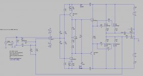
Here's a fun one for your entertainment, a MOSFET version. No need for a triple with FETs, of course, and distortion is only marginally higher than with the BJT triple. Could make for an interesting comparison. Just out of curiosity, what are the current "go-to" vertical FETs for this sort of thing? I've always simulated withe the IRFP240 / IRFP9240, but I see projects using others.
Interestingly enough, Crest doesn't have much of any decoupling between the output and the VAS stage- they clearly aren't too worried about those caps injecting power supply ripple onto the waveform. Maybe they're just relying on the CMRR of the op-amp to correct for this, and figure that it's "good enough" for their application??? I haven't been able to find any specs on the Crest 1001. The 4001 uses a similar topology. The schematic is a bit fuzzy, but it doesn't look like there's any real decoupling between the VAS and output stage. Distortion is rated at .003% at 1 kHz into 8R, and .03% 20-20k. It should be noted, of course, that Crest used ridiculously monstrous power supplies at this time.
Adding some decoupling should be quite easy. A start-up transient isn't a huge concern, since I would hope anyone building this type of amp would use some form of muting and DC protection.
Attachments
The “start up transient” I’m worried about is putting way too much bias in Q1 and Q6 till the caps charge. Way outside SOA. That puts more current than normal thru the bias regulator, and overbiases the output stage. Sure it’s short, but I would worry about it with modern output transistors. A mosfet output solution is of course more rugged, but only using the older IRFP240-ish types. The reason I don’t use them is that you can’t scale up as easily. Driving 10 pairs is actuallly harder to do cleanly than 10 BJT pairs. But keep the rail voltage sensible and they’re fine with 2, 3 or 4 pairs - you can drive them with a simple resistively loaded EF. And the lower voltage “vintage” types actually have real SOA unlike the monster-size switching types being shoved down our throats today.
I wouldn’t build a PA amp without an output relay the size of an HVAC contactor. Muting has to happen for other reasons besides the turn-on thump, too. In a hi-fi application there are valid reasons for wanting to dispense with it, if you can.
I wouldn’t build a PA amp without an output relay the size of an HVAC contactor. Muting has to happen for other reasons besides the turn-on thump, too. In a hi-fi application there are valid reasons for wanting to dispense with it, if you can.
A bit of simulation shows that yes, that start up transient is indeed awful looking- on the BJT version, each transistor would peak at nearly 8A with +/- 60V supplies.
The slower the rise time of the power rails, however, the less devastating things look. With a 100 ms rise time, things start to look a lot less nasty, suggesting that perhaps the use of a soft-start circuit might be enough to mitigate the problem.
The slower the rise time of the power rails, however, the less devastating things look. With a 100 ms rise time, things start to look a lot less nasty, suggesting that perhaps the use of a soft-start circuit might be enough to mitigate the problem.
A complicated solution but worth exploring is to disconnect the capacitors for say 100ms while the supplies rise and then reconnect them via switches or relays.
A complicated solution but worth exploring is to disconnect the capacitors for say 100ms while the supplies rise and then reconnect them via switches or relays.
I thought about that, and it wouldn't be all that difficult using relays to "pre-charge" the caps, so to speak. That said, I don't think it will be necessary. A soft-start circuit will probably be required to deal with the inrush current from a large linear power supply anyway, and it may stop the caps from being an issue in the first place.
Of course there will still be a transient, but after running a few simulations, I suspect it will be unlikely to damage anything.
Last edited:
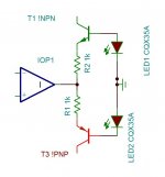
You can convert the level just by common bases.
Oh, 1k input impedance will sacrifice most of common base benefits.
Instead, lower them!
https://www.diyaudio.com/forums/solid-state/320727-opamp-common-base.html#post5386900
You can convert the level just by common bases.
Common emitter works too - and with that you don’t need an op amp that can drive 100 ohm loads (5532 is often used to drive common base level shifter).
Oh, 1k input impedance will sacrifice most of common base benefits.
Instead, lower them!
https://www.diyaudio.com/forums/solid-state/320727-opamp-common-base.html#post5386900
1K is just symbolic . The led diodes also .
- Home
- Amplifiers
- Solid State
- Op-Amp Input Stage Design