Hi Everyone thanks for helping out with my crossover questions!
Hi Galu , thank you for the optional 2nd order crossover filter !
--- I'll double check on the impedance Not sure on each of the drivers , I will go google to see how to measure that next and let you know,
So here is a little annoyance , Parts Express L-Pads, 14.00 ea. - but they just say minimum and maximum on the dial.... no numbers....
Eminence L-Pads are numbered , but 25.00 ea,.... and i asked, and the company says no difference in quality , just that plastic face plate ....
so 50.00 and you get to guess on whether the levels are matched between speakers - 100.00 and I can see if the two dials are on the same settings ....... sad state affairs ! ---- LOL . . .
Hi Everyone thanks for helping out with my crossover questions!
Hi Galu , thank you for the optional 2nd order crossover filter !
--- I'll double check on the impedance Not sure on each of the drivers , I will go google to see how to measure that next and let you know,
So here is a little annoyance , Parts Express L-Pads, 14.00 ea. - but they just say minimum and maximum on the dial.... no numbers....
Eminence L-Pads are numbered , but 25.00 ea,.... and i asked, and the company says no difference in quality , just that plastic face plate ....
so 50.00 and you get to guess on whether the levels are matched between speakers - 100.00 and I can see if the two dials are on the same settings ....... sad state affairs ! ---- LOL . . .
McBride LP-100S (M507) | Attenuator
look at the "dial" label; all adjustable L-pads have this same basic "attenuation" scale...IMPORTANT; they can come in 4 Ohm, 8 Ohm and 16 Ohm. Of course; there is no such thing as typical speaker with a constant impedance but you would choose the one closest to the stated spec. sheet impedance. Ribbon tweeters do have a very flat impedance curve but that is an obvious exception.
The Wharfedale drivers in the W70 will be nominally 15 ohm so don't sweat about it!
As for the uncalibrated L-Pads - you've got ears haven't you! 🙂
As for the uncalibrated L-Pads - you've got ears haven't you! 🙂
Hi, quick question , does it matter if you use two 4 mh coils to get a 8 mh, or is it better to use just a single 8 mh coil?
Hi, quick question , does it matter if you use two 4 mh coils to get a 8 mh, or is it better to use just a single 8 mh coil?
Best to use a single inductor 8 mH. I usually get the biggest wire gauge I can afford; especially in woofer circuits.
Jantzen Audio 8.2mH 14 AWG C-Coil Toroidal Inductor Crossover Coil
This would work but on the expensive side
Jantzen Audio 8.2mH 15 AWG P-Core Inductor Crossover Coil
A good choice at a more reasonable price
ERSE 8.0mH 18 AWG I Core Inductor Crossover Coil
I don't like 18 AWG coils in woofer circuits because the DCR is higher. If the original was 18 AWG then no big deal.
Just some quick choices from the PE site. All else being equal; it is usually best to choose an inductor with the lowest DCR in your given price range. That's why I included these 3 as examples; there are many other choices of course. The difference between 8.2 mH and 8.0 mH can most likely be ignored; it would only be a few Hertz difference in a typical woofer X/O...my 2 cents...
Hi, quick question , does it matter if you use two 4 mh coils to get a 8 mh, or is it better to use just a single 8 mh coil?
Under what circumstances do you propose to use an 8mH inductor in this upgrade? 😕
If we treat this as an academic question:Hi, quick question , does it matter if you use two 4 mh coils to get a 8 mh, or is it better to use just a single 8 mh coil?
The total inductance will only equal the sum of the inductances of the two inductors in series if they are magnetically isolated from each other.
The degree of magnetic coupling depends on the separation of the inductors and on their orientation with respect to each other.
It's complicated, but the full physics is here: https://www.electronics-tutorials.ws/inductor/series-inductors.html
- Hi Galu, sorry didn't meant to confuse you......... my bad -- 😀
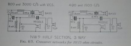
-- I found a Wharfedale guy with some experience with W70's at another forum , he's not as technically helpful as the guys here are , but he gives out helpful hints about what ideas he thinks have worked best for him... and he advocated that after I try the original crossover ....... I should then try the crossover points at 400 Hz for the woofer and mid , and 3,000 Hz for the Tweeter. --- So I went back and took a look at the Two crossovers you showed me earlier on Pg-7, (Post 66) , the first has the crossover points at 800 Hz and 3,000 Hz. . , The second schema has them at 400 Hz and 1,500 Hz. so I was trying to figure out how to combine the two of them to end up with the 400Hz and 3,000 Hz. The 400 Hz xover point for the woofer and mid was using 8 mH to do that ...... hence my reason for asking about using two 4 mH coils to get to the 8 mH I needed.
- I've been looking at how to buy all the values of the components for all four crossover ideas , but in a way that makes most of the parts all interchangeable - and so I am spending the least $ as possible...... And I think I've got a good plan.
------- But guess I should ask you if I can even do what I am trying to do -combine the two crossovers or not ......
- So, I would be changing the 4 mH coils to the 8 mH coils for the woofer and mids , and then also switch the caps on the woofer and mid from 8 Mfd's to 16 Mfd's ..... then keep the values the same at 4 Mfd's on the tweeter to get to the - 400 Hz and the 3,000 Hz crossover points, does that sound right?
- I found that fellow and a few other W70 owners over at audiokarma , actually there are quite a few there that have W60's, W70's, and W90's , so i was saying hello as I am rather new there... A few people stopped by to encourage me... of coarse I've found a lot of different opinions - and many of the guys there are more enthusiasts than technical at least that's how it seems - ( but I got to say they are big on vintage equipment over there) -- 🙂 ... unfortunately they are not as technically helpful or maybe i should say not as detail orientated as a Newbie needs though - LOL ----- So thank you everyone for your patience and help.
- Hi Galu, sorry didn't meant to confuse you......... my bad -- 😀
-- I found a Wharfedale guy with some experience with W70's at another forum , he's not as technically helpful as the guys here are , but he gives out helpful hints about what ideas he thinks have worked best for him... and he advocated that after I try the original crossover ....... I should then try the crossover points at 400 Hz for the woofer and mid , and 3,000 Hz for the Tweeter. --- So I went back and took a look at the Two crossovers you showed me earlier on Pg-7, (Post 66) , the first has the crossover points at 800 Hz and 3,000 Hz. . , The second schema has them at 400 Hz and 1,500 Hz. so I was trying to figure out how to combine the two of them to end up with the 400Hz and 3,000 Hz. The 400 Hz xover point for the woofer and mid was using 8 mH to do that ...... hence my reason for asking about using two 4 mH coils to get to the 8 mH I needed.
- I've been looking at how to buy all the values of the components for all four crossover ideas , but in a way that makes most of the parts all interchangeable - and so I am spending the least $ as possible...... And I think I've got a good plan.
------- But guess I should ask you if I can even do what I am trying to do -combine the two crossovers or not ......
- So, I would be changing the 4 mH coils to the 8 mH coils for the woofer and mids , and then also switch the caps on the woofer and mid from 8 Mfd's to 16 Mfd's ..... then keep the values the same at 4 Mfd's on the tweeter to get to the - 400 Hz and the 3,000 Hz crossover points, does that sound right?
- I found that fellow and a few other W70 owners over at audiokarma , actually there are quite a few there that have W60's, W70's, and W90's , so i was saying hello as I am rather new there... A few people stopped by to encourage me... of coarse I've found a lot of different opinions - and many of the guys there are more enthusiasts than technical at least that's how it seems - ( but I got to say they are big on vintage equipment over there) -- 🙂 ... unfortunately they are not as technically helpful or maybe i should say not as detail orientated as a Newbie needs though - LOL ----- So thank you everyone for your patience and help.
OK, now I follow. If you really want 4 mH and then end up putting two each in series for 8 mH; the DCR needs to be as low as you can afford (heaviest wire gauge). Also, the mutual inductive coupling WILL greatly affect the total inductance. Separate the two coils as far as possible; orient them 90 degrees from each other; better yet; have one vertical and the other horizontal AND at 90 degrees. I didn't open the paper above Galu suggested but I will do that now.
OK, now I follow. If you really want 4 mH and then end up putting two each in series for 8 mH; the DCR needs to be as low as you can afford (heaviest wire gauge). Also, the mutual inductive coupling WILL greatly affect the total inductance. Separate the two coils as far as possible; orient them 90 degrees from each other; better yet; have one vertical and the other horizontal AND at 90 degrees. I didn't open the paper above Galu suggested but I will do that now.
Better would be 8 mH in parallel with 8 mH to get 4 mH but then the costs would go up. All else being equal, it is better to parallel X/O components than to do series. (holds true for resistors, inductors and capacitors ALL)...
What's that old saying about too many cooks spoiling the broth?he advocated that after I try the original crossover ....... I should then try the crossover points at 400 Hz for the woofer and mid , and 3,000 Hz for the Tweeter.

So, you want 400/3,000Hz?
Use the right hand circuit, but make the tweeter capacitor 4μF instead of 8μF.
Attachments
For the record, we should note that 8mH//8mH will not necessarily give 4mH.Better would be 8 mH in parallel with 8 mH to get 4 mH but then the costs would go up.
As in the series case, the total inductance will be greater or smaller depending on the magnetic coupling between the coils.
For the record, we should note that 8mH//8mH will not necessarily give 4mH.
As in the series case, the total inductance will be greater or smaller depending on the magnetic coupling between the coils.
Yes, I addressed that already. Maximum distance; right angles even vertical/horizontal orientations. I'll see if I can find a graphic that shows these concepts...later; lunch time at the immediate moment...
Yes, I addressed that already. Maximum distance; right angles even vertical/horizontal orientations. I'll see if I can find a graphic that shows these concepts...later; lunch time at the immediate moment...
What is inductive coupling?
When using more than one inductor in a crossover, the electro-magnetic fields of the inductors can interfere with each other causing an unpleasant result. That is why it is best to keep the inductors as far apart as possible. Also, keep the fields out of phase with each other by rotating the inductors 90 degrees. It is possible to have 3 inductors out of phase, as shown below.
Attachments
What is inductive coupling?
When using more than one inductor in a crossover, the electro-magnetic fields of the inductors can interfere with each other causing an unpleasant result. That is why it is best to keep the inductors as far apart as possible. Also, keep the fields out of phase with each other by rotating the inductors 90 degrees. It is possible to have 3 inductors out of phase, as shown below.
Here is the entire article
Speaker Crossover Wiring Guide
I was also considering the direction of current flow through the series (or parallel) coils i.e. whether the fields were 'aiding' or 'opposing'.
Note that the topic of putting coils in series (or in parallel) is different from the topic of mounting independent coils on a loudspeaker crossover board.
Note that the topic of putting coils in series (or in parallel) is different from the topic of mounting independent coils on a loudspeaker crossover board.
Last edited:
Here is the link Placement of coils in crossover networksWhat is inductive coupling?
When using more than one inductor in a crossover, the electro-magnetic fields of the inductors can interfere with each other causing an unpleasant result. That is why it is best to keep the inductors as far apart as possible. Also, keep the fields out of phase with each other by rotating the inductors 90 degrees. It is possible to have 3 inductors out of phase, as shown below.
When placing coils on a crossover board, first I connect them all in series add L-meter to teh mix and move and twist coils around until measured sum is closer to the sum of individual coils.
Please note everyone, that the OP was not asking about the placement of coils on a crossover board.Hi, quick question , does it matter if you use two 4 mh coils to get a 8 mh, or is it better to use just a single 8 mh coil?
That is a well worn path!
The answer to his question lies in this tutorial: https://www.electronics-tutorials.ws/inductor/series-inductors.html
The question is "Does 4 + 4 give 8?".
Last edited:
Well, yes we can think of transformers, aiding, opposing, dot convention, etc. BUT, if the inductors are oriented correctly and far enough apart; the mutual induction/coupling goes way down and then it shouldn't matter how 2 coils are connected to one another. I'll re-read the paper above and see if I missed something. After all, Engineering school for me was in the mid 1970's; I don't claim to possibly remember everything...ha ha ha...
Well, yes we can think of transformers, aiding, opposing, dot convention, etc. BUT, if the inductors are oriented correctly and far enough apart; the mutual induction/coupling goes way down and then it shouldn't matter how 2 coils are connected to one another. I'll re-read the paper above and see if I missed something. After all, Engineering school for me was in the mid 1970's; I don't claim to possibly remember everything...ha ha ha...
Placement of coils in crossover networks
Interesting...
BTW, the above paper DOES say what I said; if there is NO mutual coupling, simple series (also, likewise) parallel formulas work. Troels shows that having inductors on an aluminum plate affects inductances of 2 coils...
- Home
- Loudspeakers
- Multi-Way
- Crossovers and which Inductor is right?