The crucial question now is:
Why do the excellent distortion-reducing characteristics of Gunderson, when applied to an unbiased (grossly non-linear) output stage, seem to desert it as the intrinsic linearity of the output stage is improved by merely providing nominal bias?
In fact, my test RB1090 gave more THD (10KHz-20KHz) when 'optimally' biased (class-B), with Gunderson in situ, than without.
It all depends on the specific circuit, Mike. Can you detail the specifics of your test? Transistors, biases, output load, etc?
The linearity of the output stage transconductance Io/(Vb - Vout) should be quite good at high bias - after all, the Vbe of the output stage transistors is linearized by the emitter degeneration resistors. With Q24 Vbe you see a raw diode junction. The Q24 Vbe will be linearized by higher bias too, of course. There may also be stability effects that are degrading your Gunderson measurements.
Needless to say, patents are granted for the novelty of an idea, not for its immediate practical benefit.
Output stage load on the VAS is easily “measured” in sim:
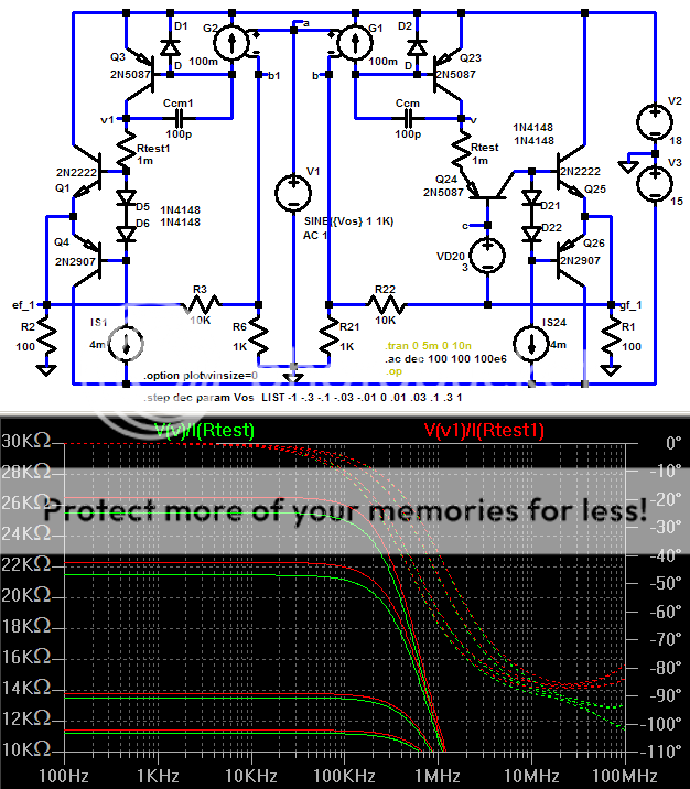
Rtest is a 1 milliOhm current sense R between the VAS and the output
The plots compare the currents from the VAS to Gunderson Q24 emitter (green, right circuit) vs the unmodified output Q base current sum (red, left circuit) to the V swing at the resp. VAS outputs
I am still stepping the bias: +/- 1 V and +/- 100mV Vos at the input V1 source give +/- 110 and 11 mA resp. output Q currents - the reason for the 4 red/green pairs of impedance traces (you can't see it in this display scheme but I verified that each closest red/green pair are in fact for the same bias condition)
The impedance seen by the VAS are very close for each bias condition despite the Q24 emitter looking like it should be low Z in the Gunderson connection
As I stated earlier the impedance of Q24’s emitter is bootstrapped out of the equation as it were
Spice transistor models aren’t however highly consistent between AC and tran analysis –the Beta plots of my Post #89 don’t show the near 2:1 variations implied by the AC plot above
http://www.diyaudio.com/forums/showthread.php?postid=966868#post966868
mikeks said:[snip]If the later were true, the net impedance at the node from which minor-loop feedback is derived would be so small that the pole-splitting mechanism, otherwise provided by minor-loop compensation, would be virtually disabled, and continuous oscillation would ensue.
Yes! That's a dead give-away! The low impedance would negate the Cdom effect for stability. Drats!
Jan Didden
Christer said:
Yes, it didn't occur to me that so long time had passed that the patent might have expired already, so your comment was appreciated. With 17 years, I guess the Optimos was published very shortly after the patent expired, so that might explain why Slone suddenly used this technique while not having mentioned it in his book, which was published earlier.
Actually it is now 20 years from date of filing which in alignment with the rest of the world. I can't remember when that was implemented tho (in the transition period it was 17 years from issue date or 20 years from filing date whichever was longer).
SteveA
jcx said:....Gunderson's...impracticality........
I think this just about sums things up nicely.

It's a wrap unless, of course, someone sorts this issue out.

Achtung!
This is incorrect after all, as you do need to provide headroom for Gunderson's BJT to operate in the presence of the bias generator.
At least four diodes (NOT zener), preferably biased by an active current source, are required for a tripled class-B/AB output stage.
mikeks said:...bias for the 'cascode' device need not be provided by a voltage divider after all....(if a 'non-complementary' TIS is used).
Just connect 'cascode' BJT directly to output rail with a small base ballast resistor...
This is incorrect after all, as you do need to provide headroom for Gunderson's BJT to operate in the presence of the bias generator.
At least four diodes (NOT zener), preferably biased by an active current source, are required for a tripled class-B/AB output stage.
janneman said:
Yes! That's a dead give-away! The low impedance would negate the Cdom effect for stability. Drats!
Jan Didden
No, it isn't! The Cdom works independent of the load impedence of the Vas/TIS! It's the voltage swing at the Vas/TIS collector that makes the Cdom work, and that does it on G's circuit also, with or without Q24. I'm going around in circles.....
So, mikeks, whether Q24 works in grounded base or whatever, as long as there is voltage swing at it's emitter Cdom works.
Jan Didden
janneman said:
......as long as there is voltage swing at it's emitter Cdom works.
Jan Didden
Well then Q24 isn't a common-base stage, which means you agree with moi.....

janneman said:whether Q24 works in grounded base or whatever, as long as there is voltage swing at it's emitter Cdom works.
Jan Didden
No...if Q24 were a true grounded base stage at the frequencies of interest, you simply couldn't connect Cdom to its emitter, as the voltage swing there would be miniscule.
mikeks said:
Well then Q24 isn't a common-base stage, which means you agree with moi.....
Indeed, it's not a CB stage. As much as I abhor it, I must confess I agree with you. On this. 😎
Jan Didden
Ref circuit post #144
What's the open loop (no R22 and no Ccm) input impedance of Q24 emitter seen by Q23 collector ?
Provocatively, for the part of the circuit around Q24 to Q26 : is that not the converse of the so-called "current feedback" circuit which has voltage input, and (apparent) current feedback : here, it's current input and voltage feedback ?
My Post #129: http://www.diyaudio.com/forums/showthread.php?postid=968002#post968002
sums up my view from my sims of this circuit’s operation – my post #144 just points out an easy way to see that Q25,6 base impedance is very closely transferred to Q24 emitter
certainly my viewpoint is that Q24 forms a type of compound transistor with Q25,6 having a local feedback loop with the particular and unusual property of having Only Voltage Gain – some prefer to explain it as enhanced Voltage compliance at Q25,6 base
Having Only Voltage Gain this “Gunderson Loop” can Only correct Vbe error of the output transistors while current gain errors (nonlinear Q25,6 base currents) are transferred thru to the new input at Q24 emitter and the resultant nonlinear load on the VAS results in the same distortion that exists without Q24 for the usual case of the output stage distortion being dominated by current gain nonlinearity
The Q24/Q25 connection has, like all other possibly functional connections of 2 transistors, been analyzed in the past – Heinlein, Holmes “Active Filters Fundamentals and Design Methods”, 1974 refers to this generalized connection as a “transparent pair” due to the transfer of the impedance at Q24 collector to its emitter and to the specific compound output transistor configuration as an “Inverse Cascode”
Gunderson 'compensation' done away with in Rotel's RB1090 by converting to straightfoward complementary cascode TIS.
Performance significantly improved.
Performance significantly improved.
Hi, Mikeks,
I experimented with this Gunderson compensation.
Usually, my power amps can take 4ohm dummyload//with 2.2uF capacitor without problem.
With this Gunderson, the amp cannot take the 2.2uF cap without oscilating the whole amp. The resistive dummy load is OK, but capacitive load is a NO.
And this cannot be compensated anywhere else in the cct. I've tried miller cap, cap to ground, cap to inv-in, none is working. I also tried the B-C cap like in Gunderson paper, also not working for 2.2uF load (parrarel or not parrarel with 4ohm dummy load).
What is your experience, is this Gunderson Compensation makes an amp cannot drive capacitive load at all?
Can anyone send me a copy of the Steven Gunderson's article "A Topology to Linearize Miller-Effect Compensated Amplifiers" JAES Volume 32 Number 6 pp. 430-434; June 1984 please?
It seems to be behind a paywall, but the patent is here: US4511857A - Output following intermediate cascode circuit
- Google Patents
- Google Patents
- Home
- Amplifiers
- Solid State
- Gunderson compensation..