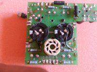
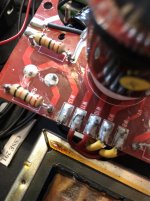
You changing first -stacked- capacitors to single Kasei.
This capacitor maximum value for 5U4GB NOT more, than 32uF, else rectifier tube would damaging.
I' afraid, that you absolutely leave second -originally stacked 470u caps: result 235uF- filtering stage.
No, 470u caps are there. There where originally places somewhere else. Look at the pictures.
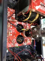
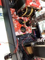
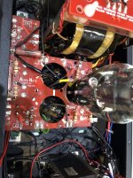
The 0.33uf coupling caps. What brands are they. AN and Jensen has been known to fail
I have tried and changed one coupling cap to Jansen Superior Z-cap 0.33uF. It does not help - voltage on 100R 6W resistor is still 42V.
Question 1, was the amplifier working correctly before you worked on it?
Question 2, if you remove the 300Bs and 6SN7s (with the 5U4 still in) what voltage do you measure across the 100R 6 watt resistor after 30 or 40 seconds?
Question 3, with the 300Bs and 6SN7s out, what actual HT (B+) voltage do you measure?
Question 2, if you remove the 300Bs and 6SN7s (with the 5U4 still in) what voltage do you measure across the 100R 6 watt resistor after 30 or 40 seconds?
Question 3, with the 300Bs and 6SN7s out, what actual HT (B+) voltage do you measure?
Question 1, was the amplifier working correctly before you worked on it?
Question 2, if you remove the 300Bs and 6SN7s (with the 5U4 still in) what voltage do you measure across the 100R 6 watt resistor after 30 or 40 seconds?
Question 3, with the 300Bs and 6SN7s out, what actual HT (B+) voltage do you measure?
Ad 1. Yes.
Ad 2. 0,15V without 6sn7 and 300b
Ad 3. 575V without 6sn7 and 300b
Last edited:
Without showing (schematic sketch) the current state this discourse is only theoretical.
The later pics showing another circuit than formers.
No, it is exactly the same as in first post. At the last pictures you can see two additional cables from 100R 6W - I have connected 20W version, and this brown one is actually disconnected from one side.
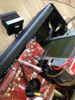
This is too low. Should be closer to 100V.Now there is 25V on each one of this four 1k5 9W resistors.
If 300B's bias voltage is 27.5V (25V on 1.5k resistors plus - I presume - 2.5V on 150R ones), it will draw excessive current.
Check the real value of these resistors with the mutimeter, and also check the 220u/100V bypass capacitors (you can temporarily disconnect them and check the current drawn by the amplifier then).
Last edited:
This is too low. Should be closer to 100V.
If 300B's bias voltage is 27.5V (25V on 1.5k resistors plus - I presume - 2.5V on 150R ones), it will draw excessive current.
Check the real value of these resistors with the mutimeter, and also check the 220u/100V bypass capacitors (you can temporarily disconnect them and check the current drawn by the amplifier then).
I have tried disconnecting both 220u capacitors on left chanel. Nothing has really changed. 25V on 1.5k resistors and 42V on 100R 6W in power supply circuit.
With the valves all back in, what is your HT (B+) reading?
About 285-295V
Last edited:
I have tried disconnecting both 220u capacitors on left chanel. Nothing has really changed. 25V on 1.5k resistors and 42V on 100R 6W in power supply circuit.
After checking all the cap, resistor values, and component orientation, I suspect you may have a slight solder short.
With power off, use a magnifying glass and make sure there are no extraneous solder drops, etc. Take your time and inspect both sides of the PCBs.
After checking all the cap, resistor values, and component orientation, I suspect you may have a slight solder short.
With power off, use a magnifying glass and make sure there are no extraneous solder drops, etc. Take your time and inspect both sides of the PCBs.
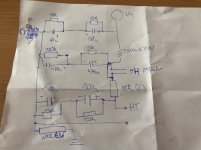
I have draw on paper current power supply circuit and check with multimeter continuity mode every connection points, one by one, everyone with everyone - my power circuit is exactly like on the picture. Maybe should I check power choke or output transformers? Output transformers are also connected to this 100R 6W resistor. How can I check if output transformers are ok? Disconnect it's HT and measure voltage on 100R 6W resistor?
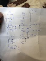
"Lower" 100R 6W (?) -you handwriting is worse than mine- both end is "ground"?
No no, sorry . On the upper left is 0 (black cable, W13 on the PCB) from power transformer, not the ground.
OK.
This 100R (is this burned?) is a safety "fuse" from secondary HV windings CT (strange solution, but it's AN )?
)?
So if schematic is correct and it is burning without tubes, there are some sorting in HV raw supply:
- shorted capacitor in one stacked line;
- shorted equalizer resistor in one stacked line;
- damaged rectifier;
- miswiring.
This 100R (is this burned?) is a safety "fuse" from secondary HV windings CT (strange solution, but it's AN
So if schematic is correct and it is burning without tubes, there are some sorting in HV raw supply:
- shorted capacitor in one stacked line;
- shorted equalizer resistor in one stacked line;
- damaged rectifier;
- miswiring.
OK.
This 100R (is this burned?) is a safety "fuse" from secondary HV windings CT (strange solution, but it's AN)?
So if schematic is correct and it is burning without tubes, there are some sorting in HV raw supply:
- shorted capacitor in one stacked line;
- shorted equalizer resistor in one stacked line;
- damaged rectifier;
- miswiring.
Burning one is this at the right and there is no problem without tubes - as I remember without tubes at this resistor voltage is less than 1V. With 6sn7 installed also there is no problem. Problems begins with inserting 300b. With one installed voltage at this resistor goes to 34-35V, with two over 42V.
- Status
- This old topic is closed. If you want to reopen this topic, contact a moderator using the "Report Post" button.
- Home
- Amplifiers
- Tubes / Valves
- Audio Note Conqueror problem
