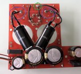
Just looking back at the original pictures you posted. Did you replace the rectifier socket? zooming in it looks like the board was damaged during surgery. Have you checked all of the traces from those connections?
Yes, socket is new, and quality of this board is very poor. All traces that where damaged I have replaced with hook up cables. I am quite positive that problem is somewhere else.

Alan had you on the right track. You have stable B+ and no crazy current draw with all the tubes out.
Redo that test with just the driver tubes, then report back the voltage across the 100 ohm resistor.
With only driver tubes installed voltage across 100 ohm resistor is 2.5-2.6V.
You wrote:
"The voltage measured at this resistor with both 300b installed is 40V. With only one 35V. "
Is this true (35V) in case of right or left tube?
If any heater regulator IC (7805) heat sink earthed, this side 300B conduct enormous current (rectifier tube limited it), and B+ falling off.
"The voltage measured at this resistor with both 300b installed is 40V. With only one 35V. "
Is this true (35V) in case of right or left tube?
If any heater regulator IC (7805) heat sink earthed, this side 300B conduct enormous current (rectifier tube limited it), and B+ falling off.
Last edited:
You wrote:
"The voltage measured at this resistor with both 300b installed is 40V. With only one 35V. "
Is this true (35V) in case of right or left tube?
If any heater regulator IC (7805) heat sink earthed, this side 300B conduct enormous current (rectifier tube limited it), and B+ falling off.
Only right 300b installed:
1. Voltage across 100 ohm resistor is 34-35V.
2. B+ is 316-317V
Only left 300b installed:
1. Voltage across 100 ohm resistor is 34-35V.
2. B+ is 317-318V
So I is quite the same - does not matter which one 300b is inserted.
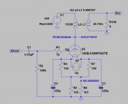
Have a look at the area in the green circle, seems the trace is broken there. And I am not absolutely sure about the right polarity of the caps I marked in the other two circles.
Yes, trace in green circle is broken. The is why there are those two hook up cables - it goes where those broken traces went. Polarity is ok - minus to minus, plus to plus.
Take the 300B bypass caps out and try again.
I should remove 220u caps and redo test just with driver tubes or also with left and then with right 300b?
Take the 300B bypass caps out and try again.
Ok, so without all 220u caps I have:
1. With left 300b installed:
a. Voltage across 100 om resistor is 31V
b. B+ is 330
2. With right 300b installed:
a. Voltage across 100 om resistor is 32V
b. B+ is 329V
3. With both 300b installed:
a. Voltage across 100 om resistor is 40V
b. B+ is 296V
4. Only with driver tubes installed:
a. Voltage across 100 om resistor is 2,58V
b. B+ is 518V
Everything is quite the same, 2-3V lower voltages (in case 1, 2 and 3) on 100 ohm resistor but still too high.
Last edited:
Are you sure it's not vice versa?4. Only with driver tubes installed:
a. Voltage across 100 om resistor is 518V
b. B+ is 2,58V
Measure those 1.5k and 150R resistors in 300B's cathodes thenYes, of course- sorry for mistake.
It's either them or heater PSU/PT winding
Measure those 1.5k and 150R resistors in 300B's cathodes then
It's either them or heater PSU/PT winding
Without removing them from the circuit I have:
1. 730 ohm on every 1k5
2. 158 ohm on every 150r
For me it looks ok - in case 1 they are connected parallel. In case 2 measure was done without 300b so they are not connected parallel. Am I right? Heater PSU for 300b also looks ok for me. Yesterday I have done some measuring and there were voltage about 4,9V with installed 300b's.
Last edited:
You are.Without removing them from the circuit I have:
1. 730 ohm on every 1k5
2. 158 ohm on every 150r
For me it looks ok - in case 1 they are connected parallel. In case 2 measure was done without 300b so they are not connected parallel. Am I right?
Let's think logically.
The amp is drawing excessive plate current - that's a fact.
6SN7 stages seem to work fine. That means 300B stages are drawing excessive plate current - like they should with just 27.5V or so bias. Even at 330V B+ they should draw 350-400mA each according to datasheet (probably a bit less in the real world, but still 200mA at least).
Under 'normal' conditions (grid is negative related to the cathode) cathode current must be equal to the plate current and it all should go to the ground via the cathode resistor network. Yet the current through the cathode resistor network in your case is just around 34mA per channel.
Those 'extra' hundreds of milliamps can't just disappear. They should go somewhere, because Kirchhoff's first law and stuff. The only path they can go is the heater PSU.
The regulators themselves might work fine and put up the proper voltage, but the whole PSU might also have some unwanted path to the signal ground - via the heatsink, or the damaged capacitor insulation, or the damaged wire insulation, or the PCB, or some unfortunate drop of solder, or even the power transformer (BTW, does it have two separate windings for 300B heaters of just one common for both channels?).
So, if it's possible, disconnect the heater PSUs from the tubes and the bias networks completely (make sure first that amp is off and all caps are discharged) and check the resistances between each (+ and -) PSU rails and the signal ground. It all should read infinity. If it's not - there's a problem.
But before that it's worth checking the voltages in the working amp directly on the 300B socket pins to exclude the OPTs and coupling caps.
You are.
Let's think logically.
The amp is drawing excessive plate current - that's a fact.
6SN7 stages seem to work fine. That means 300B stages are drawing excessive plate current - like they should with just 27.5V or so bias. Even at 330V B+ they should draw 350-400mA each according to datasheet (probably a bit less in the real world, but still 200mA at least).
Under 'normal' conditions (grid is negative related to the cathode) cathode current must be equal to the plate current and it all should go to the ground via the cathode resistor network. Yet the current through the cathode resistor network in your case is just around 34mA per channel.
Those 'extra' hundreds of milliamps can't just disappear. They should go somewhere, because Kirchhoff's first law and stuff. The only path they can go is the heater PSU.
The regulators themselves might work fine and put up the proper voltage, but the whole PSU might also have some unwanted path to the signal ground - via the heatsink, or the damaged capacitor insulation, or the damaged wire insulation, or the PCB, or some unfortunate drop of solder, or even the power transformer (BTW, does it have two separate windings for 300B heaters of just one common for both channels?).
So, if it's possible, disconnect the heater PSUs from the tubes and the bias networks completely (make sure first that amp is off and all caps are discharged) and check the resistances between each (+ and -) PSU rails and the signal ground. It all should read infinity. If it's not - there's a problem.
But before that it's worth checking the voltages in the working amp directly on the 300B socket pins to exclude the OPTs and coupling caps.
Thank you for suggestions - sound very logical. Tomorrow I will try to check it all out and give some information about results.
According to some docs, there should be two separate windings and there are two separate pair of cables - one pair for each heater psu. I did measurements on filament pins with installed 300b's - it gives ca. 4,9V.

Last edited:
#46
"If any heater regulator IC (7805) heat sink earthed, this side 300B conduct enormous current (rectifier tube limited it), and B+ falling off. "
Are you sure that each 7805 heatsink not connected to chassis?
Unbuilted the filament wiring from amplifier board check continuity of each wire to "ground".
The filament supply must be floating.
- Status
- This old topic is closed. If you want to reopen this topic, contact a moderator using the "Report Post" button.
- Home
- Amplifiers
- Tubes / Valves
- Audio Note Conqueror problem