Hello,
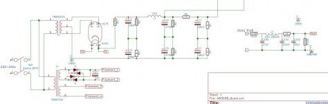
I have a problem with AN Conqueror and I can not deal with it. It is quite old unit and I have change electrolyte caps to Audio Note Kaisai and standard. After this the resistor marked on the diagram has burned out. I have changed it and it burned out again. The voltage measured at this resistor with both 300b installed is 40V. With only one 35V. The 6sn7 heater voltage is 5,9V. The 300b filament voltage is 4,9V. What can be wrong with my amp and what else should I check?
P.S. In my unit there are two more resistors that are not on the diagram. First one is 10W 1R2 between 6sn7 heater and bridge rectifier. Second one is 2W 6k8 at the positive wire that connects B+ to board with 300b and 6sn7 tubes.
If you put an electrolytic cap in backwards in the power supply, it will burn up every 100 ohm 6W resistor you put in there.
If you plug a 300B in with the fat pins not in the bigger socket holes, you might also destroy this resistor (and maybe your 300B).
If you plug a 300B in with the fat pins not in the bigger socket holes, you might also destroy this resistor (and maybe your 300B).
Thank you for answer. I have installed caps in the same way they as old ones and according to plus sings on the pcb. 300B are also correctly installed - thicker pins in thicker holes.


Last edited:
What is more voltage at this resistor without 300b's is 1,97V. Voltage on filament 300b's pins (fat ones) is 4,9V without 300b. But when I insert 300b on right one voltage keeps 4,9V but on the left one it drops to 3,7V.
check with tester the Rdc of each 300B, then test the circuit with 7805 for 300B filaments.
Mybe ydou got a problem with bridge or 7805
Walter
Mybe ydou got a problem with bridge or 7805
Walter
I have tried 3 different pairs of 300B - amp always work this same.
Circut for 300B filament:
1. For left 300b (without installed 300b):
a. AC input in bridge rectifier: 8.16V
b. DC output from bridge rectifier: 6.94V
c. DC input in 7805: 6.90V
d. DC output from 7805: 4.88V
2. For left 300b (with installed 300b):
a. AC input in bridge rectifier: 7.88V
b. DC output from bridge rectifier: 5.85V
c. DC input in 7805: 5.93V
d. DC output from 7805: 3.65V
3. For right 300b (without installed 300b):
a. AC input in bridge rectifier: 8.23V
b. DC output from bridge rectifier: 9.86V
c. DC input in 7805: 9.74V
d. DC output from 7805: 4.94V
4. For right 300b (with installed 300b):
a. AC input in bridge rectifier: 7.93V
b. DC output from bridge rectifier: 8.40V
c. DC input in 7805: 8.42V
d. DC output from 7805: 4.90V
Hello,
I have a problem with AN Conqueror and I can not deal with it. It is quite old unit and I have change electrolyte caps to Audio Note Kaisai and standard. After this the resistor marked on the diagram has burned out. I have changed it and it burned out again.
View attachment 848262
Instead of replacing the resistor, put a current meter online to check how much current is being drawn from the power supply.
Instead of replacing the resistor, put a current meter online to check how much current is being drawn from the power supply.
There is about 40V on this resistor (with both 300b installed), so I assume, based on Ohm law, that current flow is about 0,4A. Am I wrong?
There is about 40V on this resistor (with both 300b installed), so I assume, based on Ohm law, that current flow is about 0,4A. Am I wrong?
You are right, 40 volts across 100 ohms is 400mA AND 16 Watts.
So something very wrong there. No wonder the 6 Watt resistor fails...
The 5U4G has a maximum current of 225mA by the way so that will go next. The 300Bs should be at 70 to 100mA each so 140-200mA total.
I assume it was working before you replaced the caps? So re-check what you have done, the problem has to be to the right of the 100R in the diagram...
Last edited:
From the last cap of the power supply try to disconnect the cables of +Vdc to amplifier , then connect a 10 ohm resistor in series each one and look which channel draw more current.
0,4 A is too much
Walter
0,4 A is too much
Walter
You are right, 40 volts across 100 ohms is 400mA AND 16 Watts.
So something very wrong there. No wonder the 6 Watt resistor fails...
The 5U4G has a maximum current of 225mA by the way so that will go next. The 300Bs should be at 70 to 100mA each so 140-200mA total.
I assume it was working before you replaced the caps? So re-check what you have done, the problem has to be to the right of the 100R in the diagram...
Do the 300B have red plates; i.e. too much current being drawn?
Disconnect the 1K B+ resistors to the front end and measure the voltage/current drawn by the 300B cathode 1.5K parallel resistors.
You are right, 40 volts across 100 ohms is 400mA AND 16 Watts.
So something very wrong there. No wonder the 6 Watt resistor fails...
The 5U4G has a maximum current of 225mA by the way so that will go next. The 300Bs should be at 70 to 100mA each so 140-200mA total.
I assume it was working before you replaced the caps? So re-check what you have done, the problem has to be to the right of the 100R in the diagram...
At the right in power circuit are only two resistors and two caps. Do you think about them or do you think about them and whole 6sn7/300b circut?
I have changed bridge rectifier and 7805 for left 300b. Now filament voltage where 300b is inserted is about 5V, not 3,7V like before. The only thing it changes is more voltage on resistor - 42V, so now current flow from power supply is 0,42A.
The 0.33uf coupling caps. What brands are they. AN and Jensen has been known to fail
I use Duelund CAST Tinned Copper. I have in box unused Jantzen Superior z-cap - is it worth trying it?
Last edited:
From the last cap of the power supply try to disconnect the cables of +Vdc to amplifier , then connect a 10 ohm resistor in series each one and look which channel draw more current.
0,4 A is too much
Walter
Hmmm .... B+ wire for 6sn7/300b circut is common for both channels. Can you give me some more details how can I measure it?
Do the 300B have red plates; i.e. too much current being drawn?
Disconnect the 1K B+ resistors to the front end and measure the voltage/current drawn by the 300B cathode 1.5K parallel resistors.
Now there is 25V on each one of this four 1k5 9W resistors. Later I will try to bypass 1k resistor - to you mean this one after 0,33uF caps or the first one after HT? There is also 6k8 2W resistor on positive wire connecting HT (B+) from power supply. This resistor is not present at diagram.
Last edited:
One more observation - voltage at this 100R 6W resistor is about 2V for 30-40 seconds after turning the amp on. Then it goes to 42V.
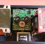
Do you have pictures from original state?
Are you sure, that HT PSU working normally?
AN generally use two wire to amplifier board: HT for power tube, B+ for driver section. Are you sure, that these wires not swapped?
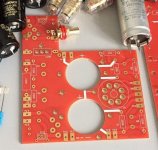
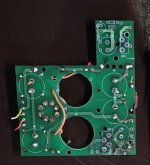
AN PSU has stacked power supply capacitors, you omitted its, changing to single Kaseis (no cap behind R4, R7). Voltages are correct amounts?
There are several wiring -without PCB trace?- on the PCB. Are you sure, that all are correct?
There are disassembled original and fake chinese AN PSU PCBs for sample.
Are you sure, that HT PSU working normally?
AN generally use two wire to amplifier board: HT for power tube, B+ for driver section. Are you sure, that these wires not swapped?
AN PSU has stacked power supply capacitors, you omitted its, changing to single Kaseis (no cap behind R4, R7). Voltages are correct amounts?
There are several wiring -without PCB trace?- on the PCB. Are you sure, that all are correct?
There are disassembled original and fake chinese AN PSU PCBs for sample.
Attachments
One more observation - voltage at this 100R 6W resistor is about 2V for 30-40 seconds after turning the amp on. Then it goes to 42V.
Do you measured anode current?
Do you have pictures from original state?
Something similar, than this Conquest PSU pic.
J&K Audio Design: Audio Note Conquest Upgrade
There are -from the right capacitor- visible the wire to the W6, which is missing in your pics.
Attachments
Last edited:
- Home
- Amplifiers
- Tubes / Valves
- Audio Note Conqueror problem