There are more alternate details about the design and noise etc. regarding TI's version - LM1084. There may be some insight to be gained there in looking at different commentaries.
Texas suggest that the difference between the 1084 and 317 types is only in the lower voltage drop of a single pass transistor versus a Darlington: https://www.ti.com/document-viewer/LM1084/datasheet/specifications#SNVS0375839
Texas suggest that the difference between the 1084 and 317 types is only in the lower voltage drop of a single pass transistor versus a Darlington: https://www.ti.com/document-viewer/LM1084/datasheet/specifications#SNVS0375839
I find these things very interesting. On semiconductors give incredibly detailed information on tl431 . Noise being shown as a detailed graph. The stability graph is excellent. It shows how to make a crowbar. And how to clone how it works.
LD1084 is low cost which helps. When I get time I will do a list of interesting devices. I will limit myself to easy to find. LM723 looks to be obsolete.
LD1084 is low cost which helps. When I get time I will do a list of interesting devices. I will limit myself to easy to find. LM723 looks to be obsolete.
LM723 looks to be obsolete.
How many do you want/need? I have a lot of them in stock 😉 I think it would be more interesting to take a look at modern devices. UA723/LM723 is excellent but high part count and the need for one or more pass transistors make it a bulky affair. IMO one would first set desired parameters and then design a PSU. When desired parameters are met only then cost is a parameter.
BTW LD1084 also exists in LT1084 by Linear Technology. And in LM1084 by TI. I wonder if there are any differences except for some TO cases that some produced and others didn't.
Last edited:
I have just bought five times forty storage drawers and a dymo label machine. I have so many parts. Soon I will be able to build almost anything. I have CMOS of many types. Soon I will have CMOS of individual types. 74HC hexinverters and 74HC4060 the favourites. I have an equal amount of similar draws to rellable. I might find my TL431 and chunky MOSFETs.
I sometimes think various devices are from the same wafer but packaged by On or Ti for example. Ti TL 431 data sheet gives 5 uV 0.1 to 10 Hz as worse case noise for Tl431 . 1/f noise no doubt? On show about 50 nV /√Hz on a graph with LF being worse. Quite handy they do that.
I sometimes think various devices are from the same wafer but packaged by On or Ti for example. Ti TL 431 data sheet gives 5 uV 0.1 to 10 Hz as worse case noise for Tl431 . 1/f noise no doubt? On show about 50 nV /√Hz on a graph with LF being worse. Quite handy they do that.
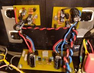
Just to remind you of my regulators for JLH69, current up to 4A, max. output voltage 25V, voltage drop min. 3V. https://www.diyaudio.com/forums/solid-state/3075-jlh-10-watt-class-amplifier-580.html#post6050539
I am currently testing La Monstre and with the same regulators it sounds wonderful, a few hundredths behind my version of the JLH69, it deserves the highest rating, the differences are in literally the details.
I think there should be no compromise around the regulator and the power supply in general if we want to get a good sound, every effort will surely pay off. I don’t have a lot of theoretical knowledge, but I’ve been doing amps since I was 14 and I’ve learned very well what good power supply in audio means.
Attachments
I totally agree. Class A amplifiers probably don't need the same things as class AB. Class A can have some RC filtering without compromising the dynamics. Class AB can tolerate more ripple. Modern class A might be more like AB. JLH is old style class A.
Member
Joined 2009
Paid Member
Modern class A might be more like AB. JLH is old style class A.
what do you mean by this, it's a very interesting comment ?
I'd say that modern Class A also includes the projects you see over on the Pass forum.
Hello all,
I found out why my Stripboard circuit didn't work, the holes in it are too big the Veropins are too loose and come 'undone'!
Having bought some of this Matrixboard from Cricklewood I found out why, for a start its thicker, stronger, the holes are smaller and the Veropins can't be pushed in with a finger nail.
I made a start using Mr Hoods pic enhanced a bit in Ps, makes it easier to follow. My goodness worra difference this is a much better way of doing things, even to anchoring the joins to the boards with little U shaped bits of wire. And if I want to alter anything the stuff will just slide apart.
You put the thought of doing something like this into my head Nigel, thanks a million.
Cheers
I found out why my Stripboard circuit didn't work, the holes in it are too big the Veropins are too loose and come 'undone'!
Having bought some of this Matrixboard from Cricklewood I found out why, for a start its thicker, stronger, the holes are smaller and the Veropins can't be pushed in with a finger nail.
An externally hosted image should be here but it was not working when we last tested it.
I made a start using Mr Hoods pic enhanced a bit in Ps, makes it easier to follow. My goodness worra difference this is a much better way of doing things, even to anchoring the joins to the boards with little U shaped bits of wire. And if I want to alter anything the stuff will just slide apart.
You put the thought of doing something like this into my head Nigel, thanks a million.
Cheers
Last edited:
what do you mean by this, it's a very interesting comment ?
I'd say that modern Class A also includes the projects you see over on the Pass forum.
Simplest example is Douglas Selfs Class A + AB that is an overbiased AB. It is very challenging for the PSU. It needs very low ripple and very low impedance. My PSU ideas for class A often have an output filter of 0R33 and 10 000uF. For A + AB I would audition that option.
The JLH is s little bit like sliding bias Class A as the music slightly raises the bias.
In some ways Class AB is better than Class A and D better than any. AB can show transients better especially into complex loads. A + AB should have no downside. I would say 2 watts A @ 8R ideal with 15 W AB. This could convert to 60 AB using an octal connector to the PSU for party mode. Same parts with different configuration. Don't use Selfs complicated design, just over bias an AB amplifier.
I suggest you also make sure there is sufficient "over heatsinking" of the output stage transistors to dissipate the increased, constant heat. I know of too many people who have taken the easy route to high-bias class AB by just cranking up the bias adjust pot. On commercial amplifier products, that often ends in trouble and unless your DIY amp. already has generous heatsinking, it may be too.
Generally, don't alter bias settings in just any type of class AB amplifier. Due to their physical layout and design, some commercial amplifiers become unstable when current is adjusted or modified to extremes such that safety circuits cease to work properly. Some will no longer stabilise at higher current settings and the usual cheap types of pots in them are not designed for more than 200 operations - no problem for an experienced tech. but a common issue for those of us who aren't so sure of what we're doing.
Generally, don't alter bias settings in just any type of class AB amplifier. Due to their physical layout and design, some commercial amplifiers become unstable when current is adjusted or modified to extremes such that safety circuits cease to work properly. Some will no longer stabilise at higher current settings and the usual cheap types of pots in them are not designed for more than 200 operations - no problem for an experienced tech. but a common issue for those of us who aren't so sure of what we're doing.
Two watts is as far as I would go in Class A. Then AB. Make the AB 20 watts perhaps. 0.5 degrees per watt heatsink stereo as they are not too high on price. Douglas Self designed a vbe (rubber diode) bias tracker for class A. Switch mode power supplies have current limiters that helps stop runaway designs.
A thermal switch can knock the bias into only class AB at perhaps 50C. This could be a couple of diodes in parallel with the vbe multiplier bias.
If you get that far the big advantage is the PSU works less hard and power supply rejection ratio of the amplifier might be superiour. The power supply is a big factor in the sound.
In terms of dynamics AB amplifiers can sound dramatically more powerful than class A of the same power. The first reason is the are much more powerful into real speaker loads over short periods of time. NAD 3020 gave 92 watts transient 2 ohms despite it's puny transformer. The second reason is well controlled AB clipping sometimes is more exciting.
An advantage of this concept is crossover distortion is broken down into two sections. This means that the feedback loop has time to recover before switching again. Technically minded people might see this as the worse of all worlds. What they steadfastly refuse to believe is their measurements are not real loudspeakers and ears. Crossover distortion is like jumping off of a cliff and expecting to walk away. Incredibly amplifiers can. It's not ideal. The feedback loop has to deal with any residual energy albeit low at crossover. That would be an argument for keeping class A part to only two watts.
In which case I'd say get some better speakers (without the 2ohm dip and with 3db more sensitivity) and keep the JLH.Two watts is as far as I would go in Class A. Then AB. Make the AB 20 watts perhaps.
All the rest is excuses.
After all, there's a reason hard rock guitar amps are class AB and it isn't because they are hifi.
(Before anyone starts, the problem with most AB designs is that they shift their bias points when clipped, so all that "perfect" small signal behaviour disappears. And you get masses of power rail intermodulation as the caps recharge)
If you really want to chase this rabbit, have a look at Peter Walker's (Quad) "current dumping" 405 which ran about 5W class A before transitioning to provide about 80W total. They insisted on patenting the idea, so it was completely ignored by the rest of industry (who stuck with the conventional Op-amp architecture)
(Or option D - buy or build a Krell KSA-50. No problems with 2ohms with a nominal 50W into 8)
Last edited:
Hello all,
Here's an altered schematic with the components I am going to use.
Having learnt a bit, listened a tiny bit, this is what I want.
I've finished filling the Matrix board
I just want about 7 or 8 Watts so I'm going to alter R2 (the resistor sticking up a bit, top right) until I get it.
It's getting really interesting now. I know now why there are such long leads on components, I'd always wondered. Being able to take one lead in on R5 and join it up both over and under the board is (to me) amazing. So much better than fiddling about with veroboard/stripboard.
Cheers
Here's an altered schematic with the components I am going to use.
An externally hosted image should be here but it was not working when we last tested it.
Having learnt a bit, listened a tiny bit, this is what I want.
I've finished filling the Matrix board
An externally hosted image should be here but it was not working when we last tested it.
I just want about 7 or 8 Watts so I'm going to alter R2 (the resistor sticking up a bit, top right) until I get it.
It's getting really interesting now. I know now why there are such long leads on components, I'd always wondered. Being able to take one lead in on R5 and join it up both over and under the board is (to me) amazing. So much better than fiddling about with veroboard/stripboard.
Cheers
Last edited:
Hello all,
I wonder if this might help re the SMPS's
A/. With my cd player connected but switched off I get a hum when the volume is turned up
B/. With it switched on the hum is not so bad
C/. With an filtered IEC three pin mains connector used on the DC side of the SMPS, condition A/. applies, no hum at all with condition B/.
D/. With the STC filter in the same position no hum at all from conditions A/. or B/.
Pic of the STC,
The sound is not affected by C/. or D/.
Cheers
I wonder if this might help re the SMPS's
A/. With my cd player connected but switched off I get a hum when the volume is turned up
B/. With it switched on the hum is not so bad
C/. With an filtered IEC three pin mains connector used on the DC side of the SMPS, condition A/. applies, no hum at all with condition B/.
D/. With the STC filter in the same position no hum at all from conditions A/. or B/.
Pic of the STC,
An externally hosted image should be here but it was not working when we last tested it.
The sound is not affected by C/. or D/.
Cheers
Simple boring question:
What capacitors would make 1969 JLH sound less bassy?
I have built several channels and I've been fiddleling with resistors R1 and R2 values. There's less distortion now but I find sound has too much bass. Not sure if has changed, but I'd like to know wich capacitors are responsable for this. I have Elna caps, wich values measure a bit higher.
Thanks
Member
Joined 2009
Paid Member
you best roll off bass using the input capacitor rather than the output or bootstrap because usually we like to avoid filtering with large caps that most likely have to be electrolytic
It's pretty hard to make the JLH bassy or have the same problem in several amplifiers without also making consistent errors like misreading parts values, wrong type semis or pinouts etc. Frankly, I would not mess with R1,2 but check that you don't have a consistent error in all the amps with a bass problem and check that the power supply remains fairly constant under load.
Otherwise, I always use a polypropylene film cap. (MKP or FKP) type at the input but ordinary MKT, MKS types are much smaller, cheaper and fine for experiments and general purpose audio.
Otherwise, I always use a polypropylene film cap. (MKP or FKP) type at the input but ordinary MKT, MKS types are much smaller, cheaper and fine for experiments and general purpose audio.
you best roll off bass using the input capacitor rather than the output or bootstrap because usually we like to avoid filtering with large caps that most likely have to be electrolytic
That make sense. Thanks for the info.
It's pretty hard to make the JLH bassy or have the same problem in several amplifiers without also making consistent errors like misreading parts values, wrong type semis or pinouts etc. Frankly, I would not mess with R1,2 but check that you don't have a consistent error in all the amps with a bass problem and check that the power supply remains fairly constant under load.
Otherwise, I always use a polypropylene film cap. (MKP or FKP) type at the input but ordinary MKT, MKS types are much smaller, cheaper and fine for experiments and general purpose audio.
The only reason I changed R1 and R2 is because the were wrong, not to change bass.
It might be my ears, or speakers. I'm pretty sure values are all right I'm ussing two car batteries in series, so no problem with power supply.
Thanks for your help.
Or the room.T
It might be my ears, or speakers.
Once in a while we need to reach for the instruments: in this case at least a true RMS mulitmeter (or CRO) and signal or function generator (there's an app for that).
In the order that is consistent with your universal philosophy do the followin
a) Listen to a range of frequencies, to find out which is "boomy"
b) Measure Vin and Vout to a range of frequencies,to see if there's a change in voltage gain (you can repeat with a small (.e.g. .25 ohm resistor in series to look at current)
Infer conclusions.
- Home
- Amplifiers
- Solid State
- JLH 10 Watt class A amplifier