Thanks! As mentioned, my focus was on making this thing work, not improving the circuit, so my hope is that there are some bits for the folks to re-use in their builds...
The DCDC converters are off-the-shelf , and I just put some common mode chokes and capacitors to remove some high frequency noise. The main job of noise removal is done by the voltage regulators on the board, see the corresponding post My private blowtorch clone
Basically, TL431-based voltage referenced, and a cap follower circuit that uses this voltage, very straightforward.
Basically, TL431-based voltage referenced, and a cap follower circuit that uses this voltage, very straightforward.
Last edited:
It is a difference amplifier with complementary JFETs, current-mirrored (kind of...) into output stages with MOSFETs in grounded gate configuration. Hope that description is correct
Self-biased four-quadrant jfet input stage with aka "folded cascode" common gate output stage.
But why do you use so powerful mosfets?
Even ZVP/ZVN3310 can do the job.
That was what John Curl (the designer) suggested in his discussion of the design. I agree, much smaller transistors could be used, and I heard of at least one case where that has worked nicely. Interesting to note that (at least in the simulation) the distortion really goes down a lot once the supply voltage is above +/-20V.
I like your description, nice summary in one short phrase!
I like your description, nice summary in one short phrase!
That was what John Curl (the designer) suggested in his discussion of the design.
Ok, could you, please, point that post, i've drowned in intersecting storylines of the huge "Blowtorch" thread.
The concept of this design are missing brilliant shine of the output common mode control loop, i suppose, that changing upper and lower resistances (seen as degenerating common base source) could be swapped to current mirrors.
There are some different approaches and it would be great to draw that redline in Blowtorch history.
Interesting to note that (at least in the simulation) the distortion really goes down a lot once the supply voltage is above +/-20V.
Yes, i suppose this is mostly due to the stabilizing huge and voltage-dependant parasitic capacitances of power MOSFETs.
I like your description, nice summary in one short phrase!
[emoji481]
I am so long in the jfet subject that I have some stock of 0,1 mA matched 2SK163/2SJ44 quads.
😉
They are far more complementary even than 2sk170/2sj74 (keeping in mind higher capacitance difference between p- and n-types).
Thanks! Yes it does sound very nice (or not "sound" at all - depending how you look at it 😀)
And, it loves taking fresh fish from a dolphin 😀
And, it loves taking fresh fish from a dolphin 😀
Ok, could you, please, point that post, i've drowned in intersecting storylines of the huge "Blowtorch" thread.
The concept of this design are missing brilliant shine of the output common mode control loop, i suppose, that changing upper and lower resistances (seen as degenerating common base source) could be swapped to current mirrors.
There are some different approaches and it would be great to draw that redline in Blowtorch history.
Good point. I printed the whole thread into a small booklet, and i am sure I have it somewhere for quick reference , exactly for these situations 😀
The current mirrors would have added a lot of complexity IMHO, but for how much improvement? high gain is not really required here, mine is running at G=8 (or 18dB) which is almost too much, especially when the power amp has too much gain. (You might ask why a line stage is needed in that case...)
And, I am not sure to remember anything about servos in JC's comments, only that he used one, I believe. I used my own servo design here, and it is needed since input DC and / or thermal fluctuations may cause the output offset to drift, which is not a good idea for DC- or transformer-coupled systems. (cap-coupled no problem, I guess, apart from that nasty power-on noise)
Yes, i suppose this is mostly due to the stabilizing huge and voltage-dependant parasitic capacitances of power MOSFETs..
yes, and maybe some linear mode operation. Sadly, most modern MOSFETs are made for switching operation, and linearity is not a concern.
[emoji481]
I am so long in the jfet subject that I have some stock of 0,1 mA matched 2SK163/2SJ44 quads.
😉
They are far more complementary even than 2sk170/2sj74 (keeping in mind higher capacitance difference between p- and n-types).
Nice, I bet that should be very useful for this type of topology. What have you built with this?
The DCDC converters are off-the-shelf , and I just put some common mode chokes and capacitors to remove some high frequency noise. The main job of noise removal is done by the voltage regulators on the board, see the corresponding post
It's a great setup 😀. I was just wondering what values you chose for the chokes and filters. Did you tune it to a specific frequency?
I printed the whole thread into a small booklet
Heh, dreambook with some detective bias...
😀
The current mirrors would have added a lot of complexity IMHO, but for how much improvement?
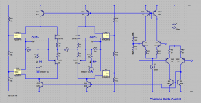
Both independent shoulders will be virtually kept relative to ground, so a way less biasing. Check attached sch.
And, I am not sure to remember anything about servos in JC's comments
Not clearly a servo, it will not remove any DC, but will symmetrize shoulders under non symmetrical input.
Sadly, most modern MOSFETs are made for switching operation, and linearity is not a concern.
Because most modern MOSFETs are high-transconductance, say order of 20 Siemens, so we just need to pick transconductance-matched pair and use it as a follower in tracking cascode output stage.
😉
Nice, I bet that should be very useful for this type of topology. What have you built with this?
Since they picked from a very large stock (more 10k pieces) they are great for differential probes and, of course, audio amplifiers with such an input stage - Ti Kan's Beta22/Beta24 and Kevin Gilmore's SuSy Dynahi.
Attachments
Member
Joined 2009
Paid Member
In hommage to ...
Thank goodness ! - imagine the longest thread(s) in living history not resulting in somebody actually building one of these 🙂
Hi Bigun, long time no hear? Doing well?
Yes, with part 2 and 3 it must be one of the best-discussed amplifiers with low gain and high output impedance ever 😀
(forgive the pun, it was much too appealing....)
Yes, with part 2 and 3 it must be one of the best-discussed amplifiers with low gain and high output impedance ever 😀
(forgive the pun, it was much too appealing....)
nice schematic.
Heh, yes, being well feedback-depth optimized it could be unbal->bal converter too. Or pick unbal signal to drive bridged push-pull output stage.
Also it could be very elegant true balanced amplifier core.
Frontend have very good intrinsic CMRR, so common-mode loop will mostly help to minimize the need for precise matching.
Literally there are four long-tailed pairs competing with each other through self-biased core.
So SuperSymmetry as well.
I notice you use the same TO247 monsters in your outputs 😀
😀
I have those on my simulation shelf with adequate models and very well matched!
Member
Joined 2009
Paid Member
Hi Bigun, long time no hear? Doing well?
Yes, thanks, I am managing alright. Just lurking around from time to time, creating a bit of trouble here and there. I really must do something constructive!
Heh, yes, being well feedback-depth optimized it could be unbal->bal converter too. Or pick unbal signal to drive bridged push-pull output stage.
Also it could be very elegant true balanced amplifier core.
Frontend have very good intrinsic CMRR, so common-mode loop will mostly help to minimize the need for precise matching.
Literally there are four long-tailed pairs competing with each other through self-biased core.
So SuperSymmetry as well.
Did you measure the harmonics of this stage, with real , not super-matched transistors?
A very useful circuit indeed.
- Home
- Source & Line
- Analog Line Level
- My private blowtorch clone