That's one nice amplifier!
Congrats, Bas.
Some multi-pin "aviation" connector wired to the box of 2mm banana sockets maybe?
Congrats, Bas.
Thingy to measure the output tube voltage across the measuring resistor. Can only measure one tube a time.
Some multi-pin "aviation" connector wired to the box of 2mm banana sockets maybe?
Thanks TG.That's one nice amplifier!
Congrats, Bas.
I could have done the bias thing better... But this solution is good enough for me.Some multi-pin "aviation" connector wired to the box of 2mm banana sockets maybe?
Last edited:
The fact that I butchered the mains transformer to fit like that. Was not a recipe for a nice looking internal build.
I wanted to also build this beautifully "inside" this time....since I used PCB's which should make that a lot easier to achieve. It was not te be.
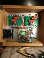
Bias supply= red wires = twisted since it has ac. And taped to the aluminium top cover with copper tape. The same for the heater wiring = blue wires.
Essentially there is a copper earth bus running diagonally on the mains transformer (but not connected...it is "floating" on the turrets). So everything goes to that (except rca input ground).
First of all from the ground "leg" of my rectifier/psu board in the middle. Then the transformer itself through from the bolt and therefore also the top plate. Then the internal screen of the transformer. The negative leg of the boards also connect to this earth bus. As I don't have rectifiers on each channel I have to be careful and connect - to earth and + to the positive part of the input. And last but not least the two 100ohm resistors from each leg of the heater supply.
Since I have a ground bus that is connected to the board...I have the connector ground for the bias xlr also connected only to the ground bus.
The output transformer just connects to the relevant connector and is not grounded anywhere. The big black heatsink is for future use.
Also the choke/resistor is bypassed with a wire. Because I want the 21st century Maida reg...and anything after that is really superfluous. But I'll probably put a big value resistor in there to get my temporary rectifier and psu board with lower voltage...so that comparison to the reg will be a more equal test.
I wanted to also build this beautifully "inside" this time....since I used PCB's which should make that a lot easier to achieve. It was not te be.
Bias supply= red wires = twisted since it has ac. And taped to the aluminium top cover with copper tape. The same for the heater wiring = blue wires.
Essentially there is a copper earth bus running diagonally on the mains transformer (but not connected...it is "floating" on the turrets). So everything goes to that (except rca input ground).
First of all from the ground "leg" of my rectifier/psu board in the middle. Then the transformer itself through from the bolt and therefore also the top plate. Then the internal screen of the transformer. The negative leg of the boards also connect to this earth bus. As I don't have rectifiers on each channel I have to be careful and connect - to earth and + to the positive part of the input. And last but not least the two 100ohm resistors from each leg of the heater supply.
Since I have a ground bus that is connected to the board...I have the connector ground for the bias xlr also connected only to the ground bus.
The output transformer just connects to the relevant connector and is not grounded anywhere. The big black heatsink is for future use.
Also the choke/resistor is bypassed with a wire. Because I want the 21st century Maida reg...and anything after that is really superfluous. But I'll probably put a big value resistor in there to get my temporary rectifier and psu board with lower voltage...so that comparison to the reg will be a more equal test.
Attachments
Last edited:
Hi Bas, what’s the copper tape you’re using? Does the copper on this tape conduct to the chassis? Where did you get this?
Regards, Gerrit
Regards, Gerrit
Hi Gerrit. Because of your question I went and checked. I thought the sticky side was conductive as well. But the adhesive is not conductive. I can't remember where I bought it. I can send you some if you like?
Did a search and both conductive and non-conductive adhesive types are sold at places like digikey and rs.
Did a search and both conductive and non-conductive adhesive types are sold at places like digikey and rs.
It's sold literally everywhere - eBay, Amazon, AliExpress, component distributors, guitar stores (it is widely used for shielding the electric guitar internals), etc.Where did you get this?
OK Bas and TG, I was indeed wondering about the conductivity using an adhesive. Can you solder it? I guess not, the layer will probably be too thin. I will look into this, as it’s an interesting idea.
Regards, Gerrit
Regards, Gerrit

Completed .... I'll do some serious listening this week.
Hi Bas, have you had time to listen and evaluate yet?
Hi Bas,
That is an amazing looking build. I think we will be mining this thread for build ideas and techniques for years to come.
Regarding those Maida regs.
Is that Tom's from neurochrome or a derivative design?
That is an amazing looking build. I think we will be mining this thread for build ideas and techniques for years to come.
Regarding those Maida regs.
Is that Tom's from neurochrome or a derivative design?
Last edited:
Yes. It's the best PushPull amp I've ever had. And it makes the last SET amp I built sound sluggish and lacking extention in highs and lows. But that is not saying much. I'm going to have a look at my SET and see what's up...highs have disappeared from when I first built it.Hi Bas, have you had time to listen and evaluate yet?
Yes. It's the best PushPull amp I've ever had.
Short and sweet! Thanks, Bas.
Transformers in the house. Yes!
Hi Mac. I've used the single ended output c-cores before. In my 6v6 single ended amp. I am very happy with them. They are not cheap. But I know the craftsman who winds them. No rush jobs by a big company. He is a one man shop.
My PP EL84 cost 225 euros per pair. Home - Vlaartronic They would have been 175 in EI core versions.
I just bought power transformers from these guys. They also seem to have nice EL84 PP. 2 Stuck Gegentakt Ausgangsubertrager ATR 15 8000 Ohm Raa UL | TBT Trafobau
Hi Bas,
Love your build.
Are these the item number for the
output transformers you bought?
VT-PP555
Thanks
Lee
Are these the item number for the
output transformers you bought?
VT-PP555
show --> https://www.diyaudio.com/forums/tubes-valves/351919-oh-baby-huey-el84-build-9.html#post6175648
Last edited:
Thanks Lee.Hi Bas,
Love your build.
I asked for those. And got the option...EI or C-core. So his C-core is not listed. You can just ask for PushPull EL84 output transformers with c-core...Are these the item number for the
output transformers you bought?
VT-PP555
Thanks Bas,
Do the C core make a big difference?
Can you recommend the psu for 230 v 240v UK ?
Lee
Do the C core make a big difference?
Can you recommend the psu for 230 v 240v UK ?
Lee
Nah. Good output transformers come in all sizes and shapes.Do the C core make a big difference?
Some alternatives:
TTG-EL84PP - Transformator głośnikowy [8kOhm] 2xEL84 PP Push-pull - Sklep Toroidy.pl
Gegentaktubertrager ATR 30 fur EL 84 | TBT Trafobau
Look for a power transformer with 250VAC/250mA secondary, 50VAC/20mA and 6,3V/5A.
Last edited:
- Home
- Amplifiers
- Tubes / Valves
- Oh no...not another Baby Huey EL84 build.