I think some more methodical testing is required - all tests should be carried out with feedback disconnected and 15KHz sinewave input with ch1 of the scope always connected to the SG output and ch2 used for test measurements:
1. I suggest we have low and high test signal levels as measured at the output of the LTP. The low should be safely inside class A operation, say 5W, and high at the maximum output level the transformer is designed for, say 20W. My maths says this should be 2.5V RMS (6.3V RMS output) and 5V RMS (12.6V RMS output). Put your scope on the speaker output first and adjust the SG output to achieve the low output figure, save the scope image and record the SG output level. Move the scope to an LTP anode and record the RMS voltage and save the image. Repeat for the high level.
2. Disconnect the V3/V4 grids from the coupling capacitors so the output stage is not working and connect the coupling capacitors to 470K resistors to earth to reproduce the EL34 grid resistance load. Repeat the checks of the LTP anode with both low and high input levels.
We should now have a set of 3 images for low and a set for high test levels, output, LTP output with EL34 grid load, LTP output without EL34 grid load.
This information should help us decide where the problem lies, for example, my guess would be the output transformer is responsible for the asymmetric ringing and possibly capacitive coupling in and around the EL34 is responsible for most of the LTP distortion.
Any NPN high 300v with hfe > 20 will do. If you wish to go down that route post a proposed schematic so we can check and make comments - and I can simulate to check and get the NFB roughly correct. That will give voltages to check your design to. Understand though that if you make changes we will need to adjust the NFB each time - so its better to settle on the bits first. I can put something together with a 6ma CCS and a valve of your choice. I prefer to-126 packages.
Last edited:
This information should help us decide where the problem lies, for example, my guess would be the output transformer is responsible for the asymmetric ringing and possibly capacitive coupling in and around the EL34 is responsible for most of the LTP distortion.
The simulation shows negative ringing on the output even through thats using a perfectly symmetric transformer, so fortunately that's probably not to blame. Its more to do with the LTP centre voltage shifting as the drive waveform becomes asymmetric. This changes the gain of the LTP and EL34 between positive and negative cycles. Its being made much worse by the output self bias, which biases down to cutoff and drops the gain of the EL34 dramatically. The reduction of gain on the negative part of the waveform make the NFB become less stable.
Last edited:
I still think it worth running these tests even if it just confirms your simulation results.
Perhaps you could adjust the input amplitude of your simulation for the 5W and 20W outputs?
Perhaps you could adjust the input amplitude of your simulation for the 5W and 20W outputs?

This would be my first go at your topology with V2 of your choice. Works out rather well actually.
The 24v zener would be 1n5359 and the CCS 2sc2611.
I'll take a look at some point soon. I've been wondering if earth loop hum could be affecting the readings I'm taking. I'm expecting my hole punches to arrive today so I can start to make the metal chassis with the aluminium that I have.I think some more methodical testing is required - all tests should be carried out with feedback disconnected and 15KHz sinewave input with ch1 of the scope always connected to the SG output and ch2 used for test measurements:
1. I suggest we have low and high test signal levels as measured at the output of the LTP. The low should be safely inside class A operation, say 5W, and high at the maximum output level the transformer is designed for, say 20W. My maths says this should be 2.5V RMS (6.3V RMS output) and 5V RMS (12.6V RMS output). Put your scope on the speaker output first and adjust the SG output to achieve the low output figure, save the scope image and record the SG output level. Move the scope to an LTP anode and record the RMS voltage and save the image. Repeat for the high level.
2. Disconnect the V3/V4 grids from the coupling capacitors so the output stage is not working and connect the coupling capacitors to 470K resistors to earth to reproduce the EL34 grid resistance load. Repeat the checks of the LTP anode with both low and high input levels.
We should now have a set of 3 images for low and a set for high test levels, output, LTP output with EL34 grid load, LTP output without EL34 grid load.
This information should help us decide where the problem lies, for example, my guess would be the output transformer is responsible for the asymmetric ringing and possibly capacitive coupling in and around the EL34 is responsible for most of the LTP distortion.
Would the effect be seen sooner if the cathode bias resistors were larger? (say 560R)The simulation shows negative ringing on the output even through thats using a perfectly symmetric transformer, so fortunately that's probably not to blame. Its more to do with the LTP centre voltage shifting as the drive waveform becomes asymmetric. This changes the gain of the LTP and EL34 between positive and negative cycles. Its being made much worse by the output self bias, which biases down to cutoff and drops the gain of the EL34 dramatically. The reduction of gain on the negative part of the waveform make the NFB become less stable.
Interesting. Does this perform better than the CCS modified 12AX7 version we looked at earlier? Do the zeners in series with the cathode bias resistors on the output provide some form of regulation for the biasing? How does the NPN transistor based CCS compared with Eli's original suggestion of using a 10m45s?View attachment 845269
This would be my first go at your topology with V2 of your choice. Works out rather well actually.
The 24v zener would be 1n5359 and the CCS 2sc2611.
Yep Eli suggestion of a 10m45s would work fine and is less components both are good enough.
Does it perform better - well its what I would design and you did not like the 'weedy 12AX7'. It does improve the drive to the EL34's so will work better at high frequencies. I went back to pentode as more gain is required and is more linear at the low plate voltages as the swing is much bigger. Does it fix the ringing - no. But is it worth the change for you - well thats up to you! I think its better practice, and if your not happy with something then it won't sound as good.
The 24v zener will stop the bias drooping at high output so much to the point it causes crossover distortion. It also reduces the variation in gain with output power so will help with the NFB. It also means you don't have to bias the EL34's so hot and risk damage. It does produce more output power - so this is quite a measurable improvement. On the down side the EL34's need to be more accurately matched and you may need to adjust the bias resistors to get the same current in each side.
The hum loop you can probably fix. Make sure you return your rectifier currents back to the transformer directly so you don't circulate them around your signal earths. Your heater supply should be balanced. If your send a oscilloscope trace of your hum we can tell whats causing it. Your input impeadance is high - does it go when you short the input out.
I can only make suggestions.
Last edited:
The 10m45 does have a nearly 2:1 ratio of current spread between devices - so you may need a trim pot to set the current.
I have not been able to find this in the 10M45S datasheet, but I agree a (1K) trimpot is needed to set the required current.
Regards, Gerrit
Regards, Gerrit
I know this datasheet. Where do you see the high tolerance in current settings? Just curious, as I know very well they exist. I’m using 4 10M45S devices in my current project (even had 6 at one point, but was able do do with one less in each channel).
Regards, Gerrit
Regards, Gerrit
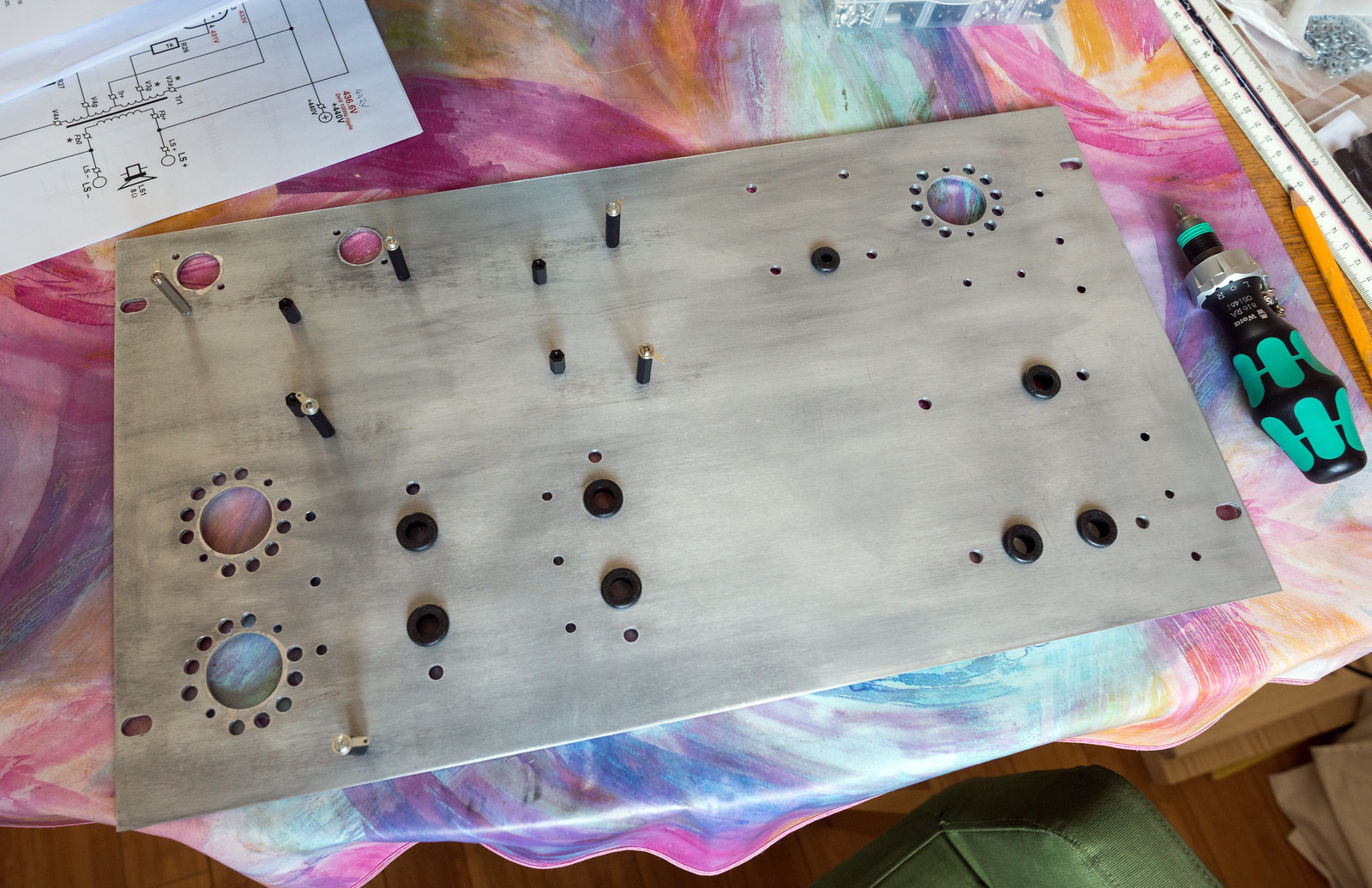
Finally got the sheet metal punches so I've made a start on my aluminium panel. This is re-purposing a 6U rack blanking cover to make the top panel. I've not put the bolt holes for the noval sockets in yet as I had no spare sockets that weren't already mounted to the wooden prototypes. I'll probably leave the cooling holes out for them as the miniature valves seem to run fairly cool. Still got all the holes for the tag strips, earth bus bar and turret board to drill.

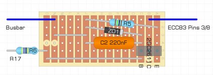
As to the CCS, is there any reason to prefer a zener over an LED using the veroboard drawing I made previously?

As to the CCS, is there any reason to prefer a zener over an LED using the veroboard drawing I made previously?
Only that a zener has a pretty tight tolerance so the current you get is quite accurate. It also places a much larger voltage across the emitter resistor so the temperature variation of the Vbe will be much lower. I avoid mosfets as you need a pot to trim them with, I reckon you can get that board even smaller.
I know this datasheet. Where do you see the high tolerance in current settings? Just curious, as I know very well they exist. I’m using 4 10M45S devices in my current project (even had 6 at one point, but was able do do with one less in each channel).
Regards, Gerrit
Sorry missed your comment.
A(P) VD = 10 V; RK = 300 Ω; (Fig. 5) 7 10 15 mA
Suits me. I'm not going to make the initial board smaller as I happen to have a spare bit that is that size. Will BZX85B6V8-TR or 1N5235BTR do in place of the SMD?Only that a zener has a pretty tight tolerance so the current you get is quite accurate. It also places a much larger voltage across the emitter resistor so the temperature variation of the Vbe will be much lower. I avoid mosfets as you need a pot to trim them with, I reckon you can get that board even smaller.
This is how it now looks.
Attachments
Finished drilling all of the holes. I've now countersunk those that need to be and fitted the standoffs.
Currently in the process of taking the wooden version apart and so far the only dodgy thing I have noticed is one of the heater connections to the EL34's wasn't actually soldered and was simply making contact by tension/touch alone. Not going to help matters but I seriously doubt that it was the cause of the wonky DC operating conditions.
One thing I did find during my hunt through all of the documents I've collected is a dynaco modified version of the mullard 5-20 that uses a 6CG7 PI. Wonder how that compares with the simulated version baudouin0 produced with the CCS tail.
Attachments
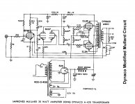
IMO, that Dynaco 6CG7 variation would do well, with a LTP tail CCS. Notice that it seems to be a "cross" of the 5-20 and HF-87. EICO accounted for non-ideal behavior of a resistor tail by employing asymmetrical plate load resistors. A tail CCS eliminates the need for that tweak.
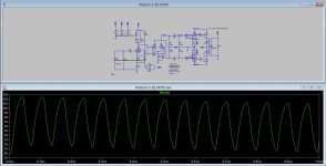
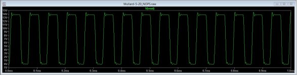
I found a 5-20 LTspice simulation on this site (somewhere) and ran a couple of tests with a modest power output. The tests are using a roughly 15KHz squarish wave.
The first is with no feedback and the output has no ringing but rise time limitations from circuit capacitance and the transformer give a very poor result.
The second is with the feedback attached and that shows the ringing that is to be expected from a responsive amplifier with lots of -ve feedback. The LTP anodes have excessive ringing as the feedback is trying to reproduce the incoming weaveform. Amazing what feedback can do...
Attachments
- Home
- Amplifiers
- Tubes / Valves
- Testing newly built mullard 5-20