Not sure what you mean by 'slow' but I would try to increase the values of C1 and C3 significantly. C1 at last 10uF (chose your favorite type) and C3 1000uF or more (bipolar electrolytic). You might have other factors depending on how 'rigid' power supply you have etc.
Have you checked for oscillations using fast transistors?
Have you checked for oscillations using fast transistors?
'Slow' mean even i turn volume 90% sound level like volume at 5%.i will try your suggestionNot sure what you mean by 'slow' but I would try to increase the values of C1 and C3 significantly. C1 at last 10uF (chose your favorite type) and C3 1000uF or more (bipolar electrolytic). You might have other factors depending on how 'rigid' power supply you have etc.
Have you checked for oscillations using fast transistors?
Unless you are trying to hear sub-bass from your amplifier, there is no point to increasing C1 (the input capacitor) size to 10uF. You may be hearing other sound effects such as those of different types and condition of electrolytic capacitor if you consider this (10 uF) amount of overkill necesssary, even where there is a nominal 47k input impedance. The standard 1uF capacitor is good down to below 20Hz and that value also allows you to fit a nice, high quality MKP film cap or even an FKP film/foil type if you can afford the best.
Note that if you fit electrolytics without any means of charging them with DC to polarize them, their function will be undefined and probably sound weird. IMHO, only use a film cap at the input. Consider that C3 is charged through R5 but where does C1 derive enough current?
Note that if you fit electrolytics without any means of charging them with DC to polarize them, their function will be undefined and probably sound weird. IMHO, only use a film cap at the input. Consider that C3 is charged through R5 but where does C1 derive enough current?
For info i use Paulb pcb.. Any big different between bc560 and bc560c?Here is the PCB pattern and overlay. It is standard Eurocard size, 100 x 160 mm.
There is also a matching power supply board, which uses the capacitance multiplier circuit on Geoff's site.
Hi all, i build jlh using this circuit. Power output use 2sc5200.power supply is +-16vdc.Problem is sound very slow? Which component need to change?
When you lower supply rail voltages like this the voltage seen at the collector of your split -phase driver transistor will be relatively low in comparison to the quiescent voltage with a single supply amplifier of this sort. I suggest reading up on Early Effect or base width modulation to understand the mechanisms involved.
I agree with that. Also I question the complexity of that version. I remember analysing the Hitachi MOSFET amplifier that has no input stage current source.On Sims had 92dB PSRR. Using a simple current source it became 110 dB and 132 dB with something complicated. As the Hitachi hardly swings any voltage there a simple RC filter would be best. Most things I see in amplifiers are done because people can. Try doing that point to point wired.
Do I understand your problem is that you are not getting much power output?
It may be worth checking the gain of your amplifier. Do you have a signal generator and AC voltmeter?
If you don't have a signal generator you could try using mains 50Hz from another (isolated, preferably double sectioned bobbin EI core type) and dividing the output voltage down to say 0.5V rms. Then measure this voltage and the output voltage from your amplifier with your meter. You should see a gain of about 12.
But this design generally needs higher voltages than the original JLH design. What output power are you hoping for?
Last edited:
Do I understand your problem is that you are not getting much power output?
It may be worth checking the gain of your amplifier. Do you have a signal generator and AC voltmeter?
If you don't have a signal generator you could try using mains 50Hz from another (isolated, preferably double sectioned bobbin EI core type) and dividing the output voltage down to say 0.5V rms. Then measure this voltage and the output voltage from your amplifier with your meter. You should see a gain of about 12.
But this design generally needs higher voltages than the original JLH design. What output power are you hoping for?
Now i use 1 single pair of power output. What voltage range i can test this circuit? And if use 2 pair power output what max voltage range? Thanks john
Regarding the complementary version of JLH10W, I agree that the standing current of 1.8A is a little high. I generally design for minimum 5 or 6 ohm loads for an 8 ohm speaker, as a safety feature, as speaker impedances can be lower than nominal.
However, if you are intending to operate the circuit with a 16 ohm load, there is scope for reducing the standing current. The emitter resistors could be increased to 0.68 ohms and the driver stage current reduced using a 220 ohm resistor for R8.
That reduces the standing current to 1A and will drive a 12 ohm impedance to at least 12V peak from a 30V supply.
In the 8 ohm version, it is to be noted that the bootstrap resistors should both be rated at 2W, but carbon film resistors are not expensive. The driver transistor dissipates about 2.5W so will need a good, but not necessarily huge, heatsink.
It might also be worth considering increasing the feedback decoupling, bootstrap and output capacitor for a better LF response.
It won't matter too much whether you have one pair, or two pairs in parallel, as the output voltage is limited by the supply rails.
The gain of the amplifier is 13, nominally, and the output may be able to reach 12V before clipping but as mjona has pointed out the supply rail voltages are a bit low for this circuit.
Using 0.5V rms input you should therefore see an output voltage of 6.5V rms. Unless you have a means of checking for clipping (oscilloscope of some description) I would not try testing with higher input voltages as you may not know what the output is doing. A clipped sinewave becomes more like a square wave and that increases the effective output voltage, which an ordinary meter won't know it is clipped.
If you have a digital meter with distortion analyser you could check if the distortion increases though, but AC mains derived voltages may not be very low distortion anyway.
A better check might even be to make a very simple phase shift oscillator with a diode-limited gain clamp. It won't be low distortion but would give you an idea of how the amplifier is performing.
There was a key word missing in my earlier post _ should have included transformer!
Regarding the complementary version of JLH10W, I agree that the standing current of 1.8A is a little high. I generally design for minimum 5 or 6 ohm loads for an 8 ohm speaker, as a safety feature, as speaker impedances can be lower than nominal.
However, if you are intending to operate the circuit with a 16 ohm load, there is scope for reducing the standing current. The emitter resistors could be increased to 0.68 ohms and the driver stage current reduced using a 220 ohm resistor for R8.
That reduces the standing current to 1A and will drive a 12 ohm impedance to at least 12V peak from a 30V supply.
In the 8 ohm version, it is to be noted that the bootstrap resistors should both be rated at 2W, but carbon film resistors are not expensive. The driver transistor dissipates about 2.5W so will need a good, but not necessarily huge, heatsink.
It might also be worth considering increasing the feedback decoupling, bootstrap and output capacitor for a better LF response.
1.change supply from 12v to 20v to 25v to 30v:nothing change
2.change r8 to 220ohm and supply 30v:nothing change
3.increase bias slowly:nothing change
No idea
Using this circuit..Hi all, i build jlh using this circuit. Power output use 2sc5200.power supply is +-16vdc.Problem is sound very slow? Which component need to change?
I change c3 to 1000uf also same..
Like gain no work.
Using this circuit..
I change c3 to 1000uf also same..
Like gain no work.
Check that the bottom end of C3 connects to your earth. If it doesn't the gain of the amplifier rather than 13 will be 1.
Also make sure the resistor values in your feedback divider network are 2.7k and 120R.
I have seen resistors where the value defining colours are hard to distinguish - like between red and orange in the multiplier bands.
I have had instances where I have had to resort to measuring the resistance to make sure I had picked the correct value.
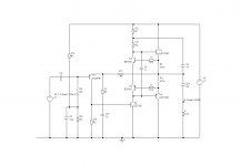
It seems I overlooked my own advice! In the complementary circuit in post # 6457 the PNP input transistor runs at 1.5mA. The emitter impedance is therefore around 17 ohms. That makes the 47 ohm limit the open loop gain, and a reduction in distortion can be achieved using 22 ohms, which is near optimum.
That leads to a reduced feedback resistor being required. In turn that means using larger capacitors. THerefore, the bootstrap, feedback decoupling and output capacitors are all increased - substantially.
The standing current of 1.8A is a little high for 8 ohms, and good performance is still possible with 1.5A which can be set using 0.47 ohm emitter resistors.
The updated circuit is attached. The simulated distortion is now 0.09% at 20kHz and 10W. With the suggested capacitors, the low frequency response extends below 10Hz.
Obviously, if an extended bass response is not needed, the capacitors can be reduced to smaller values.
Attachments
manak-
as mjona says the resistor values can be difficult to read at times, especially with the four and five band systems now common. I've managed to read a 1% resistor (brown tolerance band) in the wrong direction on 5 band coded resistors. I too have had to measure resistors more often than I used to!
as mjona says the resistor values can be difficult to read at times, especially with the four and five band systems now common. I've managed to read a 1% resistor (brown tolerance band) in the wrong direction on 5 band coded resistors. I too have had to measure resistors more often than I used to!
Member
Joined 2009
Paid Member
It seems I overlooked my own advice! In the complementary circuit in post # 6457 the PNP input transistor runs at 1.5mA. The emitter impedance is therefore around 17 ohms. That makes the 47 ohm limit the open loop gain, and a reduction in distortion can be achieved using 22 ohms, which is near optimum.
That leads to a reduced feedback resistor being required. In turn that means using larger capacitors. THerefore, the bootstrap, feedback decoupling and output capacitors are all increased - substantially.
The standing current of 1.8A is a little high for 8 ohms, and good performance is still possible with 1.5A which can be set using 0.47 ohm emitter resistors.
The updated circuit is attached. The simulated distortion is now 0.09% at 20kHz and 10W. With the suggested capacitors, the low frequency response extends below 10Hz.
Obviously, if an extended bass response is not needed, the capacitors can be reduced to smaller values.
Nice work! It looks very promising.
Perhaps it doth deserve it’s own thread if you don’t want it lost in this behemoth, dedicated to the original design.
- Home
- Amplifiers
- Solid State
- JLH 10 Watt class A amplifier