Thanks to you all. I spent the past hours going over the reference voltages, shorts to ground, resistor values. I measured both opamp input voltage delta's, but couldn't find anything out of the ordinary. Next, I took a Sony speaker and behold it plays wonderfull. So it must have been the speaker! ... but wait, I re-atached the audioengine speaker and this one is now also playing perfectly.
The polarity of the input was correct, but I did re-attach the wires. Could a poor contact to the input ground have been the cause? It is only thing I changed. But if that is the case, wouldn't there rather have been no sound at all?
Tomorrow I'll start with soldering board n°2.
VAC AC1|NAC1 is 26V
VAC AC2|NAC2 is 26V
VAC NAC1|NAC2 is 6V
With my basic knowledge I was expecting NAC1|NAC2 to measure at 0V. But I think that was a wrong interpretations of the circuit.
This I'll still do this for learning purposes 🙂.
I'll defenitely keep that in mind when buying some new speaker to pair with the FE.
The polarity of the input was correct, but I did re-attach the wires. Could a poor contact to the input ground have been the cause? It is only thing I changed. But if that is the case, wouldn't there rather have been no sound at all?
Tomorrow I'll start with soldering board n°2.
I did not understand the line input AC value, too.. 6V AC?! Should be 24-25-26-27V AC RMS, even, depending on the transformer
VAC AC1|NAC1 is 26V
VAC AC2|NAC2 is 26V
VAC NAC1|NAC2 is 6V
With my basic knowledge I was expecting NAC1|NAC2 to measure at 0V. But I think that was a wrong interpretations of the circuit.
Try to generate a 100mV AC RMS, 370Hz signal on the input, and read the output, unloaded. Should be ~ 3,1V AC RMS.
370 is not a multiple of 50, and still low enough for the meter to be correctly revealed..
This I'll still do this for learning purposes 🙂.
For what it is worth, most home speakers (85 to 90 dB/W) can be played just fine using an FE with a 10k or higher potentiometer on the input as a volume. The gain of the whole My_Ref series is 30 which is on the higher end of typical home amps.
I'll defenitely keep that in mind when buying some new speaker to pair with the FE.
Hi all
I'm evaluating the possibility to add a preamp with negative gain between my DAC based on sa9227 + pcm5102a and My_Ref.
My idea is to use this one
Balanced Volume Controller / Line Stage
with some asjustments.
I have enough space in the ampli case also for the preamp board, but not for another trafo. The idea to use the same case is especially to avoid to many connections between DAC - preamp - ampli.
Both channel of preamp needs about 120mA. So I'm thinking to use +14/-14V from one board of My_Ref. Is it possible to extract 2 pin for this? Is there some drawback?
In alternative I could use the output of one trafo, but I have some doubt about the parallel connection. Wdyt?
Both channel of preamp needs about 120mA. So I'm thinking to use +14/-14V from one board of My_Ref. Is it possible to extract 2 pin for this? Is there some drawback?
In alternative I could use the output of one trafo, but I have some doubt about the parallel connection. Wdyt?
Alas, I have experience with this. You will need to have a separate power supply for the pre-amp. The onboard +/-14V regulated supply has some headroom, but not 120mA. I found that powering 2 opamps, maybe 20 mA total, would cause stability problems depending on the opamps used.
I'm not completely clear on your trafo idea. The intended trafo layout is one, dual secondary trafo for each channel (mono block). It has proved OK to use a single, dual secondary trafo with the AC+ in parallel to both channels and the AC- on the other secondary feeding both channels in parallel. In other words, the FE board uses a dual bridge psu, so you can't have one secondary powering AC+ and AC-.
Taking an additional parallel circuit from one of the secondaries to power the pre- might work, but I am uncomfortable doing it.
In my own case, I made up a separate power supply with a separate small trafo to power an additional circuit. Something like the link, that is small.
https://uk.farnell.com/multicomp/mcta100-12/transformer-toroidal-2-x-12v-100va/dp/9530479
Jac
Thanks Jac
Let me explain better the idea about trafo. In my My_Ref I have 2 trafo, one for each channel. Each trafo has a secondary with 2x24V. So my idea is to connect one trafo to one My_Ref channel and to the preamp.
I know that it is not the best solution for the amply, but I just would avoid "too many connections" in the middle...
Unfortunately I have no space for another trafo in my box.
Got it.
To restate your idea. On one trafo, one channel of the My_Ref and the pre would be in parallel. I hope someone with more knowledge will jump in here.
You need to use both secondaries for the My_Ref, one for AC+ and one for AC-. I think that means that you would need to have a dual bridge for the pre also. For example, assume that you hooked up the pre and AC+ in parallel on one secondary. The AC+ bridge dumps negative voltage to the My_Ref ground and only has positive voltages. So, you need a dual bridge for the pre, in parallel to the My_Ref to get positive and negative voltage for the pre.
Somebody help me out here. Am I thinking about this correctly?
Jac

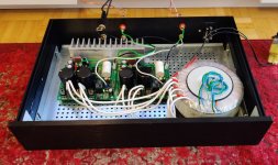
MyRef received a nice case today but i still have two issues to clarify.
1. can't find a power switch long enough to be installed into the 10mm thick panel and also to not need a larger hole than 10mm in diameter (i need to drill myself)
2. Right now the chassis is electrically floating, should i connect it to myref somehow? (heatsink pad maybe?)
Other than that nice sounding amp i have 🙂
Attachments
Last edited:
Nice.
Pgnd of each amp, to the chassis, possibly a short run.
Are You sure about the heatsink capacity?
Maybe if it is attached the bottom plate, it could do..
What kind of transformer is that?
Have fun.. You seem well set up for it.. ��
Pgnd of each amp, to the chassis, possibly a short run.
Are You sure about the heatsink capacity?
Maybe if it is attached the bottom plate, it could do..
What kind of transformer is that?
Have fun.. You seem well set up for it.. ��
Heatsink is not big enough and i plan to install a bigger one but as i'm listening to low levels is not getting very hot. The transformer is custom made on a low induction core, I believe is 350VA and is shielded. On a previous config i had 2 independent toroidals but this one sounds better.
Very nice. Would a power switch on the back work for your situation? I am guessing that the back panel is thinner and you would have a shorter run of mains power wires.
I used one one these (RadioShack # 275-0020) but I had 8mm front panels and it barely fit. Jac’s suggestion is a valid one..maybe use a power entry module with a on/off switch built in?
Dario,
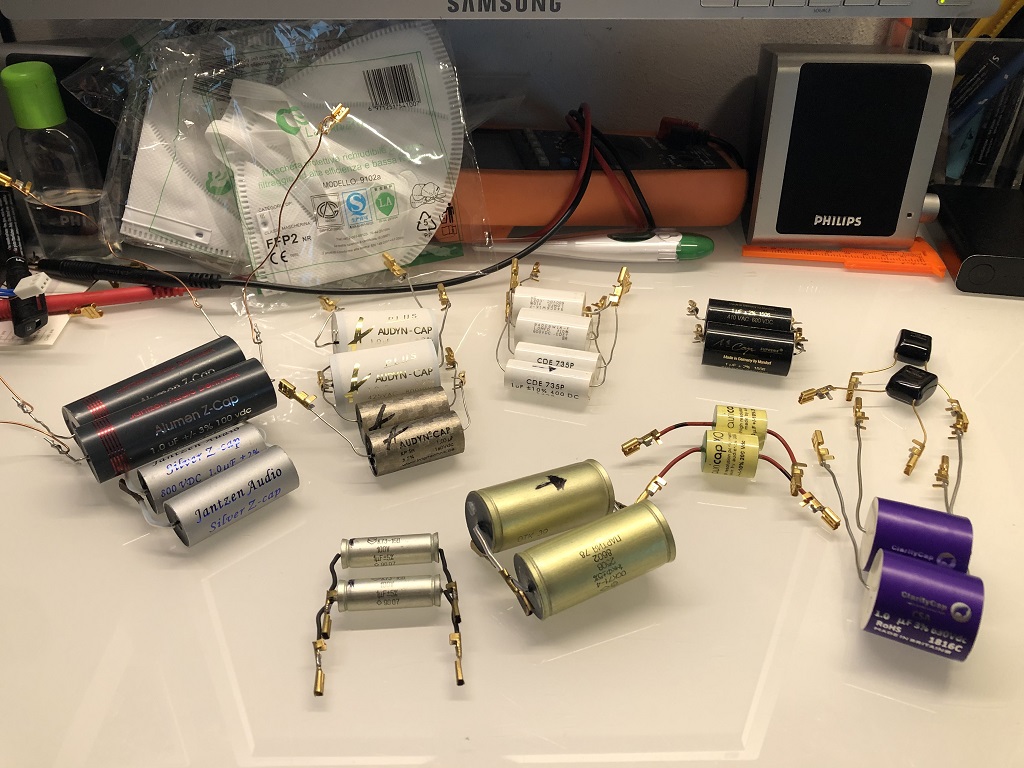
very nice collection here
would you please do a brief review for
Auricap XO
Mundorf MCap - Evo Supreme or classic
Jantzen Silver Z and Alumen
Audyn
Amtrams
very nice collection here
would you please do a brief review for
Auricap XO
Mundorf MCap - Evo Supreme or classic
Jantzen Silver Z and Alumen
Audyn
Amtrams
Just in case there are reasonibly priced caps which will gave you a nice performance boost.
I'm re-evaluating input caps including some new additions:
001-7022 - 1uF 100Vdc Jantzen Alumen Z-Cap | Hifi Collective
AMCG-060 - 1uF 250Vdc Amtrans AMCG capacitor | Hifi Collective
AXO-030: 1uF 200V Auricap XO Capacitors | Hifi Collective
CSA6-070: 1uF 630Vdc Claritycap CSA Range Polypropylene* | Hifi Collective
1501180: 1uF 160Vdc Audyn Cap KP SN Capacitor | Hifi Collective
For sure http://www.humblehomemadehifi.com/Cap.html is not a reliable source for information for coupling caps (and BTW is not supposed to be...).
Apart last two, all the other caps have been a disappointment, Audyn KP-Sn and Caritycap CSA seems both promising but I'm still evaluating.
So far the only certainty is that the Mundorf Supreme will no longer be one of the suggested caps.
Last edited:
Sorry for the late answers, I'm pretty busy in these weeks.
I would avoid.
using PS from boards will result in problems, like Jac experienced in the past.
Using secondaries for two loads will possibly work but a lot of noise will affect both, impairing performance, I would prefer a cable and two cabinets...
No, PGND should be left floating or connected to chassis via a loop breaker (see build guide).
A 'floating' heatsink must be connected to safety ground or the HSGND pad on boards (only if each board has a dedicated heatsink).
Still re-evaluating since I've changed signal and power cables.
MCAP EVO are not on the list, though.
Both channel of preamp needs about 120mA. So I'm thinking to use +14/-14V from one board of My_Ref. Is it possible to extract 2 pin for this? Is there some drawback?
In alternative I could use the output of one trafo, but I have some doubt about the parallel connection. Wdyt?
I would avoid.
using PS from boards will result in problems, like Jac experienced in the past.
Using secondaries for two loads will possibly work but a lot of noise will affect both, impairing performance, I would prefer a cable and two cabinets...
Nice.
Pgnd of each amp, to the chassis, possibly a short run.
No, PGND should be left floating or connected to chassis via a loop breaker (see build guide).
A 'floating' heatsink must be connected to safety ground or the HSGND pad on boards (only if each board has a dedicated heatsink).
would you please do a brief review for
Auricap XO
Mundorf MCap - Evo Supreme or classic
Jantzen Silver Z and Alumen
Audyn
Amtrams
Still re-evaluating since I've changed signal and power cables.
MCAP EVO are not on the list, though.
Last edited:
Sorry for the late answers, I'm pretty busy in these weeks.
I would avoid.
using PS from boards will result in problems, like Jac experienced in the past.
Using secondaries for two loads will possibly work but a lot of noise will affect both, impairing performance, I would prefer a cable and two cabinets...
Thanks Dario
I'm already buying another case and another trafo 😉
MyRef received a nice case today but i still have two issues to clarify.
1. can't find a power switch long enough to be installed into the 10mm thick panel and also to not need a larger hole than 10mm in diameter (i need to drill myself)
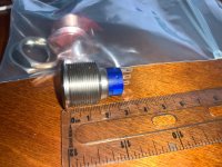
Take a look here: TE Connectivity 5 A Pushbutton Switches | Mouser
These are expensive ,but very nice , you might find similar for less money .
Attachments

Thanks @asuslover for your advices. Did you managed to drill mounting holes on your own or you paid a specialized firm to do this?
I didn't.... I could work with wood , but not with metal, so I remember I asked a friend to do it for me. These switches are 19mm wide( perfect size for a man finger, but Anti-Vandal series is available in sizes of 16, 19, 22 and 25mm ) drill bits that size are not cheap.
Try Step Bits for larger holes. They bite a small chunk with each step.
There are issues with thick metal, 1/4” face plates, and use with a drill press and clamp.
There are issues with thick metal, 1/4” face plates, and use with a drill press and clamp.
- Home
- Amplifiers
- Chip Amps
- My_Ref Fremen Edition - Build thread and tutorial