Good to know, can it be tube related or shold look from somewhere else?That sounds good. However your HT is low.
Dont be embarrassed, that's exactly what this thread is for!I am embarrassed to say that was it😱 A couple of them apparently.
Looking good with the tester Oliver.
It's just a learning experience. If you only make the 1 mistake of not flowing a join properly, out of all the work youve done, that's a great achievement!
I have just measured across the same point you requested recently, @slavSeems like drain sits too low , I'm at work today so having just a quick look at it , you need higher DS voltage to be in linear part of characteristic , not sure how much play is there with load - you might need to ask Alan , I'd also recalculate gain and have a look at input capacitance.
Here's what I got. Multimeter set to 20vDC:
Source: L - 1.72v R - 1.72v
Drain: L - 0.36v R - 0.36v
Multimeter set to 200v DC
R6: L - 107v 82v R - 107v 82v
How high shold the HT be?That sounds good. However your HT is low.
What ac voltge should I use?
The HT should be about 230-240V DC.
This can be measured across C4P or from the cathode (square pad) of D5P or D6P to ground.
This can be measured across C4P or from the cathode (square pad) of D5P or D6P to ground.
The HT should be about 230-240V DC.
This can be measured across C4P or from the cathode (square pad) of D5P or D6P to ground.
Measured C4P and its 216V. Transformer is 175, but when tubes lit on, it drops to 172-173.
Any hints what to look for, when HT is low?
I guess there is some CRC filtering , you could play with resistance to bring voltage to required level but I'd investigate current draw beforehandMeasured C4P and its 216V. Transformer is 175, but when tubes lit on, it drops to 172-173.
Any hints what to look for, when HT is low?
I have just measured across the same point you requested recently, @slav
Here's what I got. Multimeter set to 20vDC:
Source: L - 1.72v R - 1.72v
Drain: L - 0.36v R - 0.36v
Multimeter set to 200v DC
R6: L - 107v 82v R - 107v 82v
It seems you draw around 7.5mA through the valve , what's the designed working point ?
At what Idss did you match them , must be quite high close to 20mA
I cant remember the values of the FETs other than they were identical.It seems you draw around 7.5mA through the valve , what's the designed working point ?
At what Idss did you match them , must be quite high close to 20mA
As for the designed working point, we'll have to wait for Alan on that.
I have just measured across the same point you requested recently, @slav
Here's what I got. Multimeter set to 20vDC:
Source: L - 1.72v R - 1.72v
Drain: L - 0.36v R - 0.36v
Multimeter set to 200v DC
R6: L - 107v 82v R - 107v 82v
I looked at your readings again - Drain , Source should be the other way round , I guess is just a typo?
Probably lolI looked at your readings again - Drain , Source should be the other way round , I guess is just a typo?
Measured C4P and its 216V. Transformer is 175, but when tubes lit on, it drops to 172-173.
Any hints what to look for, when HT is low?
Have you connected the secondary winding to the outer two connections?
Sounds like you might have half wave rectification.
Yes, measured both of them, 9.6-7 volts.Have you connected the secondary winding to the outer two connections?
Sounds like you might have half wave rectification.
Attachments
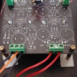
In that photo a number of the solder joints look "cold" and/or starved to me.
For instance:
D6P
HS2P (middle)
HS1P (right)
R6P (bottom)
C4P
Maybe these are good from the other side. I'm just seeing what I can see. Worth checking?
For instance:
D6P
HS2P (middle)
HS1P (right)
R6P (bottom)
C4P
Maybe these are good from the other side. I'm just seeing what I can see. Worth checking?
I connected secondary 9.5-0-9.5 as seen on the the photo of my previous post. Black ones are 9.5 and orange 0V. Measured from the poles and got 9.6 to 9.7.I don't understand 9.6-7 volts. On What?
Will resolder later, thanks for pointing out. I did add more solder later in several places, just to be sure, so looks of it might be deceiving.In that photo a number of the solder joints look "cold" and/or starved to me.
For instance:
D6P
HS2P (middle)
HS1P (right)
R6P (bottom)
C4P
Maybe these are good from the other side. I'm just seeing what I can see. Worth checking?
On the red wires you should have around 175V AC.
Check D5,6,7 and 8 for polarity.
I measured the (primary) red wires on terminals, so this is correct.Measured C4P and its 216V. Transformer is 175, but when tubes lit on, it drops to 172-173.
Was super careful when installing diodes, they should be right polarity. Will check again, just to be sure.
- Home
- Source & Line
- Analogue Source
- Bigbottle Phonostage Builders thread