One thing I did notice was that there was an at least 10db to 15db drop in level between the exciter area and the top and bottom of the panel.
So it is acting mainly as a point source,I will see if adding 50x50 pva helps spread the dml across the panel,and check the weight increase when totally dry.
Not sure if it is because I've rigidly mounted my ply panel,but the volume across the whole ply panel seems to hold up very well.
Steve
Thanks for all the measurement info Steve! You mentioned a drop in level between the exciter and top and bottom of panel. I noticed a similar drop on my panels and wondered if it's typical of most DML panels or related to my design? Could you clarify what you meant by the volume holds up well across the whole panel because it seems to contradict the first statement?
Thanks, Dave
Guys, any tips on how you can tell if your panels are suffering from standing waves?
Tone sweeps and graphs? Or is it just obvious from suckage when you listen to music?
Tone sweeps and graphs? Or is it just obvious from suckage when you listen to music?
Hi intaud.
My photos in post 1862 on page 187 shows the HF on my rigid ply panels 2ftx3ft reaching the edge areas .
My comments about my very light 16x9inch low grade eps panels ,was because I was surprised by the fast drop off in volume across the surface in such a small panel.
The very soft eps is obviously damping the dml ,like trying to put an exciter on a sponge (not quite)it does travel across the panel but at a much lower level.
50x50mix of pva and water should help here,more on that later.
What are your panels and exciter and size and what have you done in general.
Covid.
Look at my post 1865.
Thanks Spedge, that’s a great tip.
BTW, check out my latest cable management “innovation” !
This seems to help with the exciter wobble by taking the wire weight right off the exciters.

BTW, check out my latest cable management “innovation” !
This seems to help with the exciter wobble by taking the wire weight right off the exciters.

Covid.
Your three pegs are probably altering your panel response,you could mount them in a positive area if you can monitor the response?
I usually use thin wire to go to the exciter for less strain,and hang the wire from the pole I use to support the panel,not too short or long a distance.
If you have a way of measuring your panel response it would be easy to slide the peg around and watch the response change,could help fill any dips you may have ,let's say ,below 400hz,I usually us AA batteries stuck on with blu-tack ,they slide well .
Steve
Hello,
Should check out this link the goldy - AER Loudspeakers They are using acrylic plate and their bbx exciter.
Cheers
Steve
Should check out this link the goldy - AER Loudspeakers They are using acrylic plate and their bbx exciter.
Cheers
Steve
3000 eur per driver seems excessive, but i havent heard them, so perhaps it isn't!
Pricelist - AER Loudspeakers
Pricelist - AER Loudspeakers
This one is likely much more expensive
Gobel High End - Ultra High End Speakers and Cables
Proprietary 9-layer membrance (wood, carbon fiber and other material) with laser cut slots around the edges to reduce reflection
Gobel High End - Ultra High End Speakers and Cables
Proprietary 9-layer membrance (wood, carbon fiber and other material) with laser cut slots around the edges to reduce reflection
Hello,
Should check out this link the goldy - AER Loudspeakers They are using acrylic plate and their bbx exciter.
Cheers
Steve
Interesting that it requires a subwoofer. I'm not surprised since I think for full range DML requires low end reinforcement. I don't understand how a company can charge those prices without at the very least providing frequency response graphs!
Thanks, Dave
Intaud.
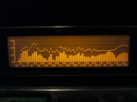
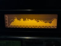
You were asking about sound level dropping off across the panel surface so I dug out an old panel I haven't used for some years now,it has two sides with 1inch bracing and no bracing on the other two,the panel was2x3ft 3mm.
Here are a few photos of the response using peak hold ,the first picture shows the response 3inches in front of the exciter area ,dotted line ,the lower solid line is 3inches also but near the edge of the panel,a considerable drop.
The second photo again dotted line from exciter area,but the solid line from the braced side, hardly any drop at all ,this was a worst case scenario,to show some drop, otherwise not a lot of difference,there is actual gain across the whole panel though!
Because I use a single10watt exciter ,the extra gain was handy ,to match the volume of my other panels but without getting hot.
Steve
Attachments
Intaud.
You were asking about sound level dropping off across the panel surface so I dug out an old panel I haven't used for some years now,it has two sides with 1inch bracing and no bracing on the other two,the panel was2x3ft 3mm.
Here are a few photos of the response using peak hold ,the first picture shows the response 3inches in front of the exciter area ,dotted line ,the lower solid line is 3inches also but near the edge of the panel,a considerable drop.
The second photo again dotted line from exciter area,but the solid line from the braced side, hardly any drop at all ,this was a worst case scenario,to show some drop, otherwise not a lot of difference,there is actual gain across the whole panel though!
Because I use a single10watt exciter ,the extra gain was handy ,to match the volume of my other panels but without getting hot.
Steve
Steve,
Thanks for the additional measurement info. I haven't measured yet but I think I hear more drop off in the high end of the frequency range as I move to the edge of my panels. Your measurement appears to correlate this with greater drop-off above 10k. By the way my panel design is described in post #1730.
Dave
Intaud.
I'm a bit mystified about the correlation of more drop off above 10k?
On my rigidly mounted panel photos ,the opposite is shown.
On the photos of the unclamped side the drop off is mostly across the whole frequency range equally.
My p!y panels use no damping measures,the opposite in fact.
Your design uses heavy damping ,intentionally or not,heavy cardboard glued to the cf ,foam damping soaking up frequencies,the rigidity of the cf 1ft width could also cause problems too.
For me it all gets too complicated,I use simple panel design to produce very good sounding panels ,that need no eq,or in some cases can be tweaked to look pretty ,when measured ,but without altering the overall sound.
If I remember rightly I did try to lower the peak in the response above 10k on my rigid ply panel,with eq,but noticed very little if any difference to the sound,so ended up leaving it alone for simplicity.
A good sound dml is one that needs no ,or very little eq,if it's not broken don't fix it.
Steve
Here is another interesting DML Speaker https://i.pinimg.com/736x/7c/fd/a3/7cfda3d5b7ec0b47ed3c8c44de1bf0de.jpg
Cheers
Steve
Cheers
Steve
I did a youtube search with a 1 month filter for dml speakers / flat panel speakers as i figured more people would be tinkering lately. I found a few:
tiny balsa panel on a box
YouTube
slim and tall ply panels:
YouTube
plywood with resin (i think)
YouTube
basic 3 mm ply
YouTube
sand on a plate
YouTube
tonewood (idk, sound seems pretty terrible)
https://www.youtube.com/watch?v=uFnWQgmuwUo
guitars in stereo (older)
https://www.youtube.com/watch?v=eN5gihTm5lk
When is a DML not a DML?
This is a post about one of the patents I have been diving into during the lock down. Apologise to @Veleric and @Spedge as I owe you guys some feedback which I will deliver, promise, but this patent has captured my attention for number of reasons which I hope to make clear.
The patent is Patent No.: US 6,826,285 B2 (45) Date of Patent: Nov.30, 2004 and filed by one Farad Azima of NXT fame.
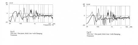
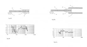
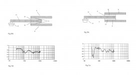
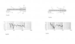
This patent focusses on the use of damping on flat panels with exciters and the effect damping has on frequency response and output amongst other issues. I have copied some screenshots from the patent of responses that Azima measured for a variety of damping methods which you can see shows that damping has a significant effect on the frequency response.
However, the bit that surprised me is the following statement from the patent
“In contrast, the present invention stipulates substantially terminating the panel Structure at the panel boundaries, ideally to absorb incident bending wave energy. This is tantamount to an infinite panel with a finite acoustic aperture imposed on it. This is a significant departure from the prior art and in fact an antithesis to a modal object.”
In short, a DML with damping is no longer a DML operating in the modal regime but instead acts as a Bending Wave transducer. Think ripples that spread out and disappear at the damped edge. This sounds like a dramatic departure from what we understand, certainly what I understood previously. However, if you read the patent there is a lot to learn from it which is why I am bothering to bring it to your attention.
Some of the outtakes I found interesting are
1. The frequency range peaks and dips can be significantly smoothed by using damping. See the images attached. @Veleric this is the point you were making ages ago but I thought you would like to see another confirmation : )
2. The frequency response can be ‘tuned’ by the use of damping, different damping methods effecting different frequency ranges. See the images attached
3. By careful use of damping the panel can act both as a DML and a Bending Wave transducer at the same time, the operational mode changing from one frequency range to another
4. The use of damping can extend the low frequency reach of a panel-obviously of great interest to me.
Now some of the points above have been reported by others who have discovered some of the beneficial effect of damping, but this patent is very useful in that is contains guidance and formula that we might use to fine tune the results we get and also explore other areas like the mixed DML/Bending Wave mode of opperation.
For those who want to dig deeper the patent is easy to read and comes with a stack of diagrams and measured responses making it easy to comprehend.
I hope this is of interest
Back to being a hermit and stay safe all.
Burnt
This is a post about one of the patents I have been diving into during the lock down. Apologise to @Veleric and @Spedge as I owe you guys some feedback which I will deliver, promise, but this patent has captured my attention for number of reasons which I hope to make clear.
The patent is Patent No.: US 6,826,285 B2 (45) Date of Patent: Nov.30, 2004 and filed by one Farad Azima of NXT fame.
This patent focusses on the use of damping on flat panels with exciters and the effect damping has on frequency response and output amongst other issues. I have copied some screenshots from the patent of responses that Azima measured for a variety of damping methods which you can see shows that damping has a significant effect on the frequency response.
However, the bit that surprised me is the following statement from the patent
“In contrast, the present invention stipulates substantially terminating the panel Structure at the panel boundaries, ideally to absorb incident bending wave energy. This is tantamount to an infinite panel with a finite acoustic aperture imposed on it. This is a significant departure from the prior art and in fact an antithesis to a modal object.”
In short, a DML with damping is no longer a DML operating in the modal regime but instead acts as a Bending Wave transducer. Think ripples that spread out and disappear at the damped edge. This sounds like a dramatic departure from what we understand, certainly what I understood previously. However, if you read the patent there is a lot to learn from it which is why I am bothering to bring it to your attention.
Some of the outtakes I found interesting are
1. The frequency range peaks and dips can be significantly smoothed by using damping. See the images attached. @Veleric this is the point you were making ages ago but I thought you would like to see another confirmation : )
2. The frequency response can be ‘tuned’ by the use of damping, different damping methods effecting different frequency ranges. See the images attached
3. By careful use of damping the panel can act both as a DML and a Bending Wave transducer at the same time, the operational mode changing from one frequency range to another
4. The use of damping can extend the low frequency reach of a panel-obviously of great interest to me.
Now some of the points above have been reported by others who have discovered some of the beneficial effect of damping, but this patent is very useful in that is contains guidance and formula that we might use to fine tune the results we get and also explore other areas like the mixed DML/Bending Wave mode of opperation.
For those who want to dig deeper the patent is easy to read and comes with a stack of diagrams and measured responses making it easy to comprehend.
I hope this is of interest
Back to being a hermit and stay safe all.
Burnt
Attachments

Last edited:
Hi BurntCoil
Thank you for posting this patent. The thing with the different damping methods is interesting me very much. Especially the one at picture 28B. It looks for me, that the panel is hold at the edge with a variety of different damping material and it's characteristics could compared to a spring (Goodmans Axiom 80) or e. g. the corrugated paper surrounding of a speaker cone. Could such a damping method be made at the bottom edge only?
Eric
Hi Eric, great question!
From the patent it looks like the assumption is that the damping would be applied to the perimeter. However it includes the option of applying damping to additional positions on the panel. This may be an example of expansive patent claims to provide additional protection, there is no data presented on this additional approach from what I can see.
So your question is a very interesting one an adds another area to explore.
I have copied and pasted what I believe to be the most pertinent description of the 'ideal' system from the patent below.
Incidentally the Gobel speakers now make more sense to me. The slots cut into the perimeter are designed to prevent reflections so the panel is operating in bending wave mode not DML mode. The Gobel also has a huge XO circuit with lots of passive EQ which always puzzled me, but looking at some of the peaks and dips seen in some of the frequency responses in the patent maybe some detailed EQ is needed with this approach?
Burnt
From the patent it looks like the assumption is that the damping would be applied to the perimeter. However it includes the option of applying damping to additional positions on the panel. This may be an example of expansive patent claims to provide additional protection, there is no data presented on this additional approach from what I can see.
So your question is a very interesting one an adds another area to explore.
I have copied and pasted what I believe to be the most pertinent description of the 'ideal' system from the patent below.
“Ideally the panel system should have a structure with a mechanical impedance all around its boundaries designed to terminate the mechanical impedance of the panel. This will result in the full absorption of the bending wave energy reaching the boundaries.
StiffneSS or structural impedance profile across the panel or by the inclusion of forms of edge termination.
In one form of the present invention, a bending wave panel is provided with a medium for reducing the reflection of bending wave energy from at least a portion of a boundary of the panel.
In another form of the bending wave panel of the present invention, there is a gradual reduction or increase in damp ing or impedance across a panel.
In another form of the bending wave panel of the present invention, a reduction or increase in damping or impedance across a panel is substantially linear.
In another form of the bending wave panel of the present invention, a reduction or increase in damping across a panel is substantially non-linear and can be, for example, exponential.
In another form of the present invention, a bending wave panel comprises a medium which presents an impedance to a bending wave in the panel.
References here in to impedance include references to reactance and/or resistance.
References herein, both explicit and implicit, to acoustics or Sound include references to infrasound and ultrasound.
In practice, a combination of the above two techniques may be used to achieve the desired performance. In both cases, the damping Structure may be deliberately designed 55 by Specifying the material and/or the Structure of it to be frequency dependent in order to achieve a given acoustic target-for example it may be desirable for the panel to become modal at higher frequencies. “
Incidentally the Gobel speakers now make more sense to me. The slots cut into the perimeter are designed to prevent reflections so the panel is operating in bending wave mode not DML mode. The Gobel also has a huge XO circuit with lots of passive EQ which always puzzled me, but looking at some of the peaks and dips seen in some of the frequency responses in the patent maybe some detailed EQ is needed with this approach?
Burnt
Last edited:
Just to add that the following section from the patent suggests that one edge treatment is sufficient if your panel is beam like. Your suggestion of damping on the bottom edge only could work and its certainly worth investigating.
c) Analysis of the reflection coefficient and System damping factor for a simple beam model facilitates the prediction of the effects of different treatments on the behaviour of a panel.
Thank you for investigation, sounds good, hopefully my project too : )
Will check out the honeycomb cardboard (2 x 40x80cm) with Visaton EX 60 R / 8 exciters (just ordered).
Will check out the honeycomb cardboard (2 x 40x80cm) with Visaton EX 60 R / 8 exciters (just ordered).
Do you guys think that the Goebel infinite slicey disk approach would make the panel significantly softer? I guess it might since presumably you lose the sound that would have been generated by the reflections?
I’m tempted to try it on my 2 * 4 * 3mm panels but would to think hard about how.
I’m tempted to try it on my 2 * 4 * 3mm panels but would to think hard about how.
- Home
- Loudspeakers
- Full Range
- A Study of DMLs as a Full Range Speaker