Re-building a FH11 board after blowing up the channel. I don’t have the 0.47r 2W resistors (2 in parallel for each mosfet).
Don’t have these exact ones in my stash - can I use a single 0.33r 5W resistor? What effect will this have on the amp? Will it damage anything?
Don’t have these exact ones in my stash - can I use a single 0.33r 5W resistor? What effect will this have on the amp? Will it damage anything?
Sure, or 0.22R works too. Even mismatched a bit won't hurt and might even make it sound sweeter as asymmetry introduces higher second harmonic relative to third.
just stating the obvious, do it for both channels and not just the blown one.
It’s a four channel amp - I was going to do the other symmetrical amp (both used on woofers), but was going to leave the other two with the 0.47(x2). Is that ok, or a must change on all 4 channels? Thanks for the help guys.
my personal opinion is to have same sound signature all through out the system, if they are producing same music/ same frequencies.
It may not even be discernible when the other two 2 channels are used on say (mids and tweets?).
Like in a Home Theater, some use a different and powerful amp for the sub and lower power but high SQ amp for all satellites
It may not even be discernible when the other two 2 channels are used on say (mids and tweets?).
Like in a Home Theater, some use a different and powerful amp for the sub and lower power but high SQ amp for all satellites
my personal opinion is to have same sound signature all through out the system, if they are producing same music/ same frequencies.
It may not even be discernible when the other two 2 channels are used on say (mids and tweets?).
Like in a Home Theater, some use a different and powerful amp for the sub and lower power but high SQ amp for all satellites
Thanks for clarifying - I will just order the 0.47r resistors to match the other channels and save any experiments to a 2-channel amp I will build soon.
Hi Folks,
I have asked JPS64 to work up a new layout for the popular FH9 using all the latest tricks of the trade from a professional designer. We will make it based on the FH9HV and have certain component upgrades and things to make installation easier. It will be called the FH9HVX. Stay tuned...
Cheers,
X
I am starting a new thread on the FH9HVX over in the GB forum.
FH9HVX - Budget Conscious 100w Class AB for Lean Times
PSU15
hello sir mile e made the psu15 low drop but at the output I can not regulate the voltage I have a 55vdc transformer and tested with zener 15v-12v and 8v and nothing and designed the prasi version any suggestion sir to be able to regulate the voltage like in psu5 or psu10
thanks
hello sir mile e made the psu15 low drop but at the output I can not regulate the voltage I have a 55vdc transformer and tested with zener 15v-12v and 8v and nothing and designed the prasi version any suggestion sir to be able to regulate the voltage like in psu5 or psu10
thanks
Attachments

hello sir mile e made the psu15 low drop but at the output I can not regulate the voltage I have a 55vdc transformer and tested with zener 15v-12v and 8v and nothing and designed the prasi version any suggestion sir to be able to regulate the voltage like in psu5 or psu10
thanks
Terry has built it and works fine; he reported the pot value should be 5k or 3k.
+ check other things also.
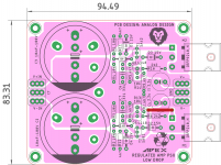
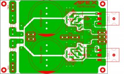
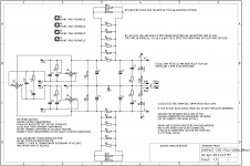
Retro Amp 50W Single Supply
No, please study the schematic carefully...
1. using on-board rectifiers b1 /b2:
cs/cx , cx', cs' and rs , rs' are the quasimodo snubber components (optional).
2. off board rectifiers:
connect the off-board first bridge rectifier's +ve WIRE to the B1+ terminal towards the top AND rectifier's - wire to the B1's - terminal.
connect the off-board second bridge rectifier's + wire to the B2's + terminal and then rectifier's - wire to the B2's - terminal.
RB and RB' are the bleeder resistors...
R1 to R7 on positive and R1'-R7' on the negative side are in parallel...
So you would be better off using 1 ohm , 1W to 2W resistors.
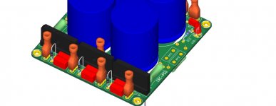
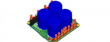
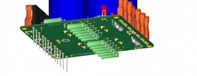
I will make a 3D on how to mount components...
edit: 3-d pics attached
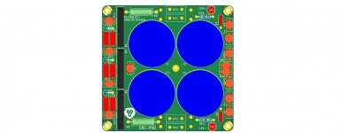
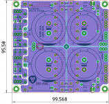
here is a version of above quoted crc with either CT trafo or dual secondary trafo. though slightly larger at 95 mm x 99mm, it can now take up 35mm caps, 6 x 3W resistors or 2 x 5W resistors.
The center bridge to be used only when CT trafo is to be connected.
regards
prasi
Attachments
Last edited:
hello sir mile e made the psu15 low drop but at the output I can not regulate the voltage I have a 55vdc transformer and tested with zener 15v-12v and 8v and nothing and designed the prasi version any suggestion sir to be able to regulate the voltage like in psu5 or psu10
thanks
Have you measured across the trimmer? I had a solder bridge that shorted the trimmer and locked my output at 42V. I know this circuit works because I just built one for the Apex AX6 Retro amp.
hello sir mile e made the psu15 low drop but at the output I can not regulate the voltage I have a 55vdc transformer and tested with zener 15v-12v and 8v and nothing and designed the prasi version any suggestion sir to be able to regulate the voltage like in psu5 or psu10
thanks
Transformer must be 2x55V AC and there is no bridge rectifier on the pcb... post picture with complete wirenig.
Transformer must be 2x55V AC and there is no bridge rectifier on the pcb... post picture with complete wirenig.
hi mr mile...
about ax 17/ax15/a14/ax14/a33/A23/a40
how much bias curent?
there are no exact information...
and about a33 for dc ofset use 470k pot and for bias 500R pot?
Last edited:
Transformer must be 2x55V AC and there is no bridge rectifier on the pcb... post picture with complete wirenig.
I modified Prasi's layout to add a bridge and fuses. Please check for accuracy.
Attachments
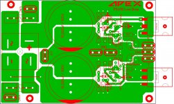
Hi Terry, nicely done. The gate trace is flooded with copper on negative side , there is need to isolate it from copper pour.
regards
prasi
regards
prasi
Also trimmer and 4k7 are unconnected.
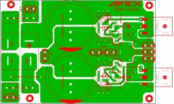
These should be better.
Attachments
here is a version of above quoted crc with either CT trafo or dual secondary trafo. though slightly larger at 95 mm x 99mm, it can now take up 35mm caps, 6 x 3W resistors or 2 x 5W resistors.
The center bridge to be used only when CT trafo is to be connected.
regards
prasi
GERBERS and SCH for the CRC PSU. it can be used with either center tapped transformer or dual secondary transformer.
regards
prasi
Attachments
Last edited:
- Home
- Amplifiers
- Solid State
- 100W Ultimate Fidelity Amplifier