
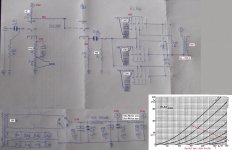
Your power transformer looks to be 480volts into a bridge rectifier. This will result in 600+ volts in the high voltage. This is WAY too much. You will probably want about 275 volts.
I'd use a source follower with STF3LN80K5 or something with more transconductance than just a single ECC88 triode section (maybe both triodes in the tube)
Your power transformer looks to be 480volts into a bridge rectifier. This will result in 600+ volts in the high voltage. This is WAY too much. You will probably want about 275 volts.
180 that looks like 480, I think.
I like it. I'm planning something similar but with four SV83 and perhaps a DHT driver. I'm going to use the One Electron UBT-1.what do you think about it?
What output transformer are you planning to use?
Last edited:
180 Vac gives about 230-240 Vdc. Is that enough?
The filament supply should be earthed to prevent hum.
You should at least reverse the pins of the ECC88 in view of the maximun cathode to heater voltage (pins 1, 2 and 3: 150 V / pins 6, 7 and 8: 50 V). And maybe increase the 1K resistor in the power supply since the ECC88 does not need a high anode to cathode voltage (90 V is enough).
The grid of the first triode misses its grid leak resistor.
The cathode resistors of the EL84's are on the low side. In the Philips datasheet it says 270 Ohm at Va = 250 V but under those conditions the EL84 runs a bit 'cold'.
Last edited:
I have 2 universal output transformers, from 600 ohm to 10000 - 25w
I'm trying to use what I already have at home... i have an 180v transformer, but i have a 200v transformer too... i have a lot of EL84 and a pair of ECC88, but
I am ready to store any suggestions and changes to the project...
I'm trying to use what I already have at home... i have an 180v transformer, but i have a 200v transformer too... i have a lot of EL84 and a pair of ECC88, but
I am ready to store any suggestions and changes to the project...
Well, there is room for improvement 😀what do you think about it?
Mona
Attachments
tks Mona!
all the improvements are strongly welcome...
Why only 830 ohm? Shouldn't it be around 1730?
all the improvements are strongly welcome...
Why only 830 ohm? Shouldn't it be around 1730?
I have 2 universal output transformers, from 600 ohm to 10000 - 25w
I'm trying to use what I already have at home... i have an 180v transformer, but i have a 200v transformer too... i have a lot of EL84 and a pair of ECC88, but
I am ready to store any suggestions and changes to the project...
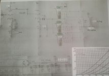
Will your SE transformer carry 116mA of idle current?
See the red loadline ΔVa = 100V (250-150) and ΔIa = 40mA.tks Mona!
all the improvements are strongly welcome...
Why only 830 ohm? Shouldn't it be around 1730?
Ra =ΔVa / ΔIa = 100 / 40 = 2k5 for one tube, 3 in parallel asks for 2500 / 3 = 833,3333333...Ω
You can use 1730 Ω , gives more ΔVa but much less ΔIa resulting in low output power.(try drawing a loadline)
Mona
The cathode resistors raise the output impedance and reduce output power - bypassing will help both.
Ra is plate resistance of 3 parallel EL84s. Load should be 2-3 times that. Higher gives less power, less distortion.
Ra is plate resistance of 3 parallel EL84s. Load should be 2-3 times that. Higher gives less power, less distortion.
You can link the 15k cathode follwer resistor to the cathode of the first stage with adjustable resistor and eliminate the partial bypass capacitor. the adjust provides you the means to cancel the negative feedback by a positive one and adjust as tuning the inverse nonlinear character of the output.
The dealer sold them To me as 170 ma max. They have 10 different primary pins... I can get 800 ohms impedance approx. with intermediate pins.
I don't have 2 identical trimmers ... I could try on only one channel but then I would find myself with the same problem.
Attachments

I do not like something about the circuit of post # 18,
Why?
If you connect 3 EL84 Cathodes together to a Common Self Bias Resistor, you will get 3 different Cathode currents.
Unless you can match the 3 EL84 tubes in Triode mode, at the exact plate voltage, and the exact bias voltage of that amplifier circuit.
Hint: Put a 1 ohm 1% sense resistor in series with each cathode and the single 82 Ohm resistor.
Then use a precision DMM to measure the millivolts across each of those three 1 Ohm resistors. In that case, mV = mA
Please tell me when you are able to find three EL84 tubes with matched currents . . . OK?
If you can not find a matched trio (3 matched), then use individual self bias.
And three parallel EL84 tubes with an unbypassed 82 Ohm cathode resistor, will cause the total of the parallel plate resistances to go up by 1640 Ohms.
Do you want that?
Much better to use 3 individual 246 Ohm cathode resistors, and to use 3 individual bypass capacitors.
That will better match the cathode currents, and will lower the parallel plate resistance, rp.
I am not familiar with the 4SH1L Pentode that you are using in Triode Wired mode.
But with 3 EL84 tubes in triode mode, there is a significant Miller Effect Capacitance from the 3 control grids, to the 3 screen grids, plus 3 plates.
The 4SH1L plate resistance, rp, has to drive all of that capacitive reactance. The capacitive reactance can be quite low at high frequencies (causing high frequency roll off?).
"You should make things as simple as possible, but no simpler" - Albert Einstein
Last edited:
Hello.
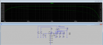
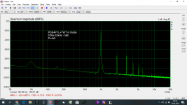
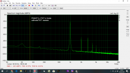
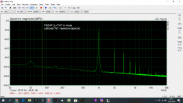
My English is too weak to get into the discussion. I always match tubes because setting the same resting currents alone doesn't give anything because THD increases significantly. Tubes work in certain voltage ranges on the control grid and not just at one point. But for the transparency of the system can be changed to 3 separate resistors. Adding capacitors in the EL84 tubes leads to a significant increase in THD (6W=2.45%) I would have to change the input tube. As for the frequency response, there is no problem, I have PSE4P1L and an upper limit above 30kHz. I apologize for my English. Piotr
My English is too weak to get into the discussion. I always match tubes because setting the same resting currents alone doesn't give anything because THD increases significantly. Tubes work in certain voltage ranges on the control grid and not just at one point. But for the transparency of the system can be changed to 3 separate resistors. Adding capacitors in the EL84 tubes leads to a significant increase in THD (6W=2.45%) I would have to change the input tube. As for the frequency response, there is no problem, I have PSE4P1L and an upper limit above 30kHz. I apologize for my English. Piotr
Attachments
Last edited:
- Home
- Amplifiers
- Tubes / Valves
- EL84 Parallel SE