This is an experimental investigation into the feasibility of a very compact point source horn using a tractrix profile and a nice RAAL ribbon tweeter. The design follows earlier methodologies described in the Trynergy thread and also the PRV 5MR450NDY thread. I used the PDF horn plans developed earlier and scaled the plans by a factor of about 0.33x to 0.35x in order to generate the profiles used here. I stretched the nominally square throat out in the vertical and horizontal directions to accommodate the rectangular aperture of the RAAL ribbon aperture. This is a private commissioned design so I have been asked to keep certain info private, such as the specific RAAL model number. But I think one can adapt this concept to almost any ribbon tweeter given appropriate crossover points.
The horn dimensions are about the size of a sheet of letter paper (8.5in high x 11in wide x 7.5in deep). The envisioned frequency range is 500Hz to 20kHz+ with a crossover from 1.8kHz to 2.6khz. Integration with an externa woofer will provide bass below 500Hz.
The midrange will be handled by dual Faital Pro 3FE22 (8ohms) wired in parallel. However, I have found that this combo produces almost too much sensitivity. At 2.0Vrms and 0.5m, the microphone was clipping and my ears were ringing. I think the peak sensitivity was probably about 105dB at 2.83v. As a result, I had to back off the excitation to about 0.63Vrms to keep things bearable for measurements. An observation, consistent with my earlier efforts to use an AMT for a Synergy style horn was that there is very little horn-gain for the tweeter. Maybe 2dB... I think this results from the very small low mass diaphragm that does not pistonically "pump" the air column at the throat vs. a dynamic driver that acts more as a piston and hence experiences typically 10dB of horn gain.
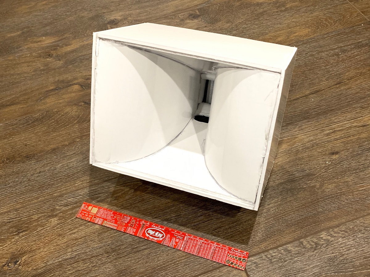
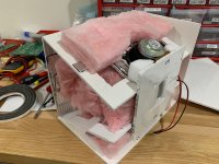
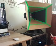
Here is the completed protoype Trynergy horn made out of Elmer's thick paper-faced foam core material. I tried the glossy finish foam core (vs matte) and although it looks great, the hot melt glue does not adhere well as the surface is glossy via a wax coat treatment. If I did it all over again, I would use the matte finish.
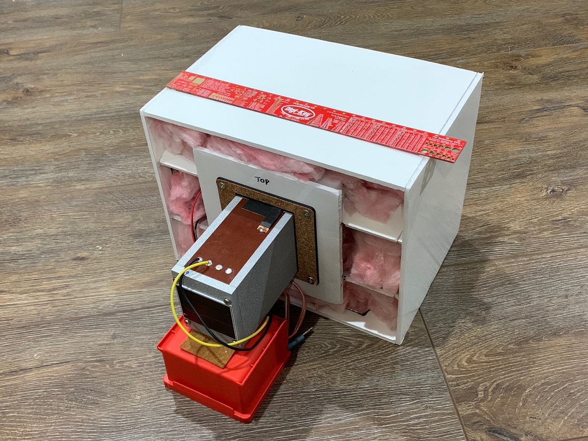
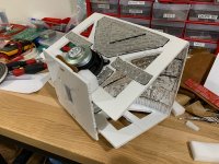
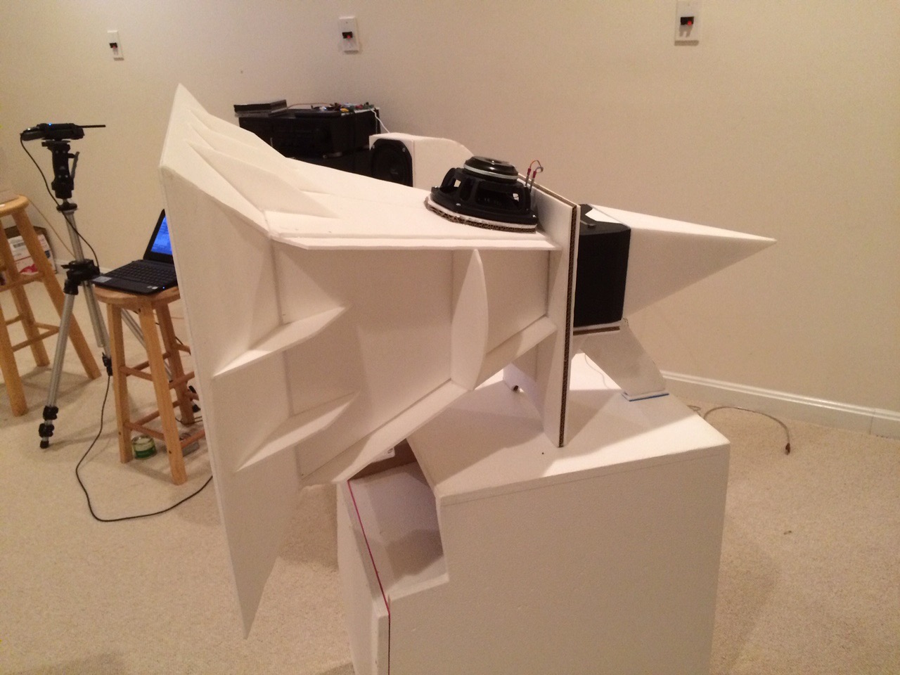
Rear view of the prototype showing open back stuffed with fiberglass in a manner similar to the microTrynergy. This provides enough of an enclosure to allow the mid range to go down to 500Hz with a -12dB/oct falloff. This is exactly where I wanted the crossover to be, so it worked out well. The bass drivers can be anything, but a pair of nice 8in woofers in open face saeled or reflex or TL etc can take this from 500Hz down to circa 50Hz easily. A set of woofers above and below for a WHW (woofer-horn-woofer) arrangemennt might work out real well for a point source system. The horn is surprisngly rigid once all glued together. The two top and bottom driver moutning plates serve large rib reinforcemnts to make the box quite stiff, yet surprisngly light weight.
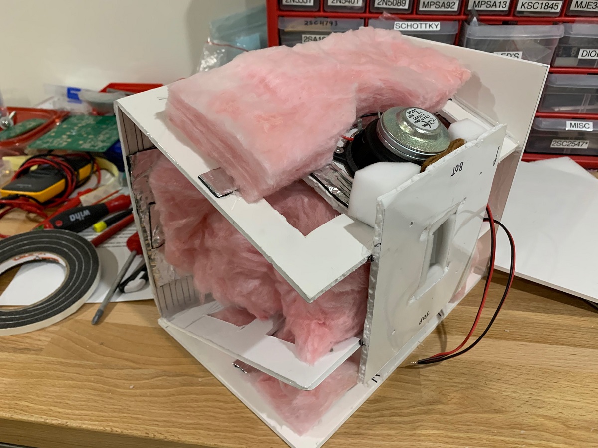
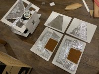
Here are the construction details showing the liberal use of Noico mass-loaded butyl for resonance reduction. The panels and especially the horn walls are very dead sounding under the 'knuckle rapping' test. This will be evident in the very low THD vs frequency plots:

Noico on the side panels as well:

Lot's of pink fiberglass sound dampening is used throughout, some felt right behind the driver magents, and some use of melamine foam at strategic locations:
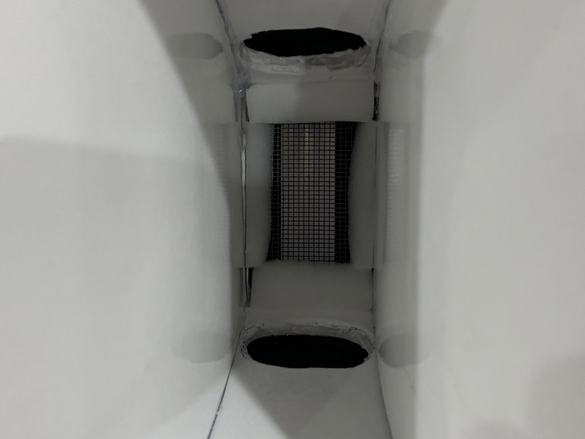
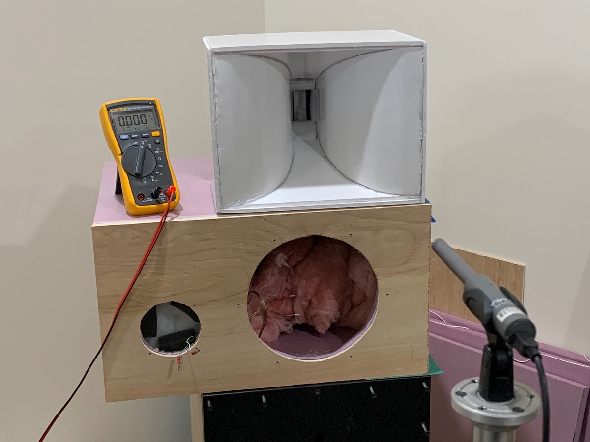
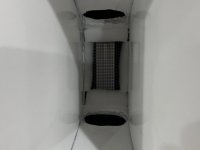
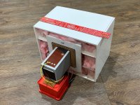
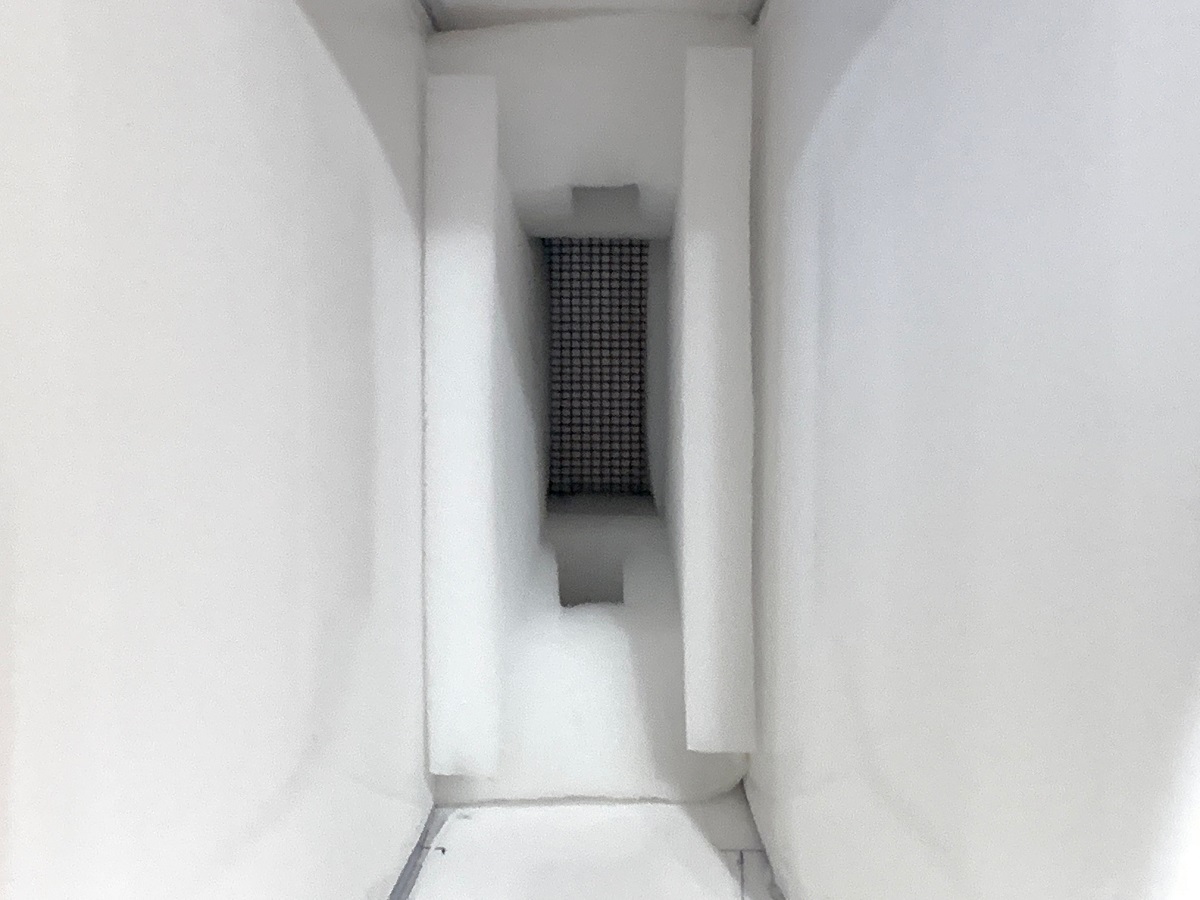
Here is a closeup of the throat and mid-range injection ports (20mm x 40mm at 23mm from throat plane). Throat is approx 40mm wide x 70mm tall. The location was made as close as physically possible given the bezel diameter of the 3FE22:
Getting measurements made using UMIK-1 at 0.5m to avoid room reflections:
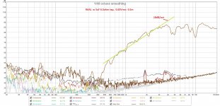
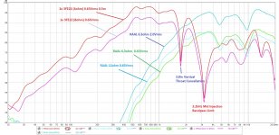
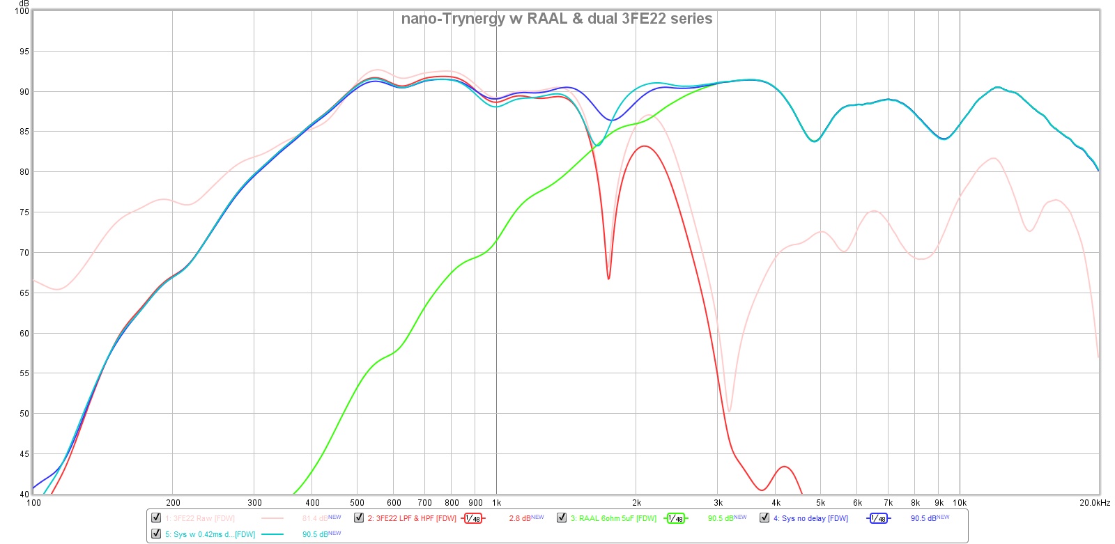
Measured response with freq dependent window (FDW) 6 cycles for mids and ribbon at various excitation levels and impedance taps:
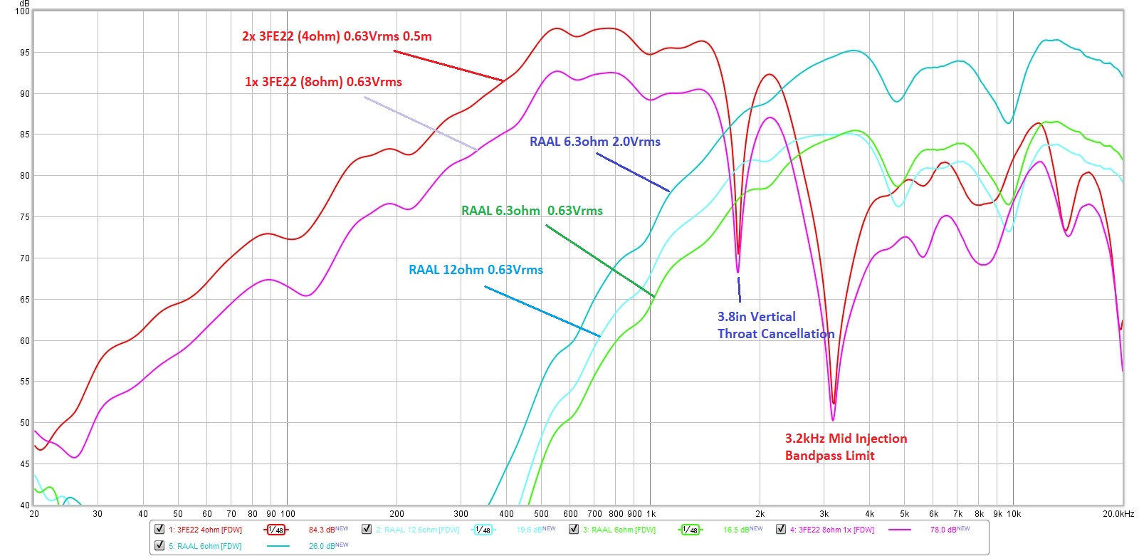
The mid range has a sharp dip at 1.74khz, which I believe corresponds to the reflection cancellation from the top and bottom walls at the throat injection point (3.8in). The goal was to get up to 3kHz if possible.
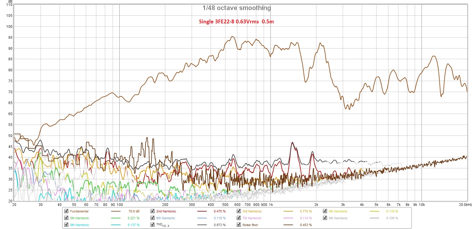
Here is the THD vs frequency of one 3FE22 running at only 0.63Vrms - about 87dB at 1m ( a very comfortable SPL) and showing very low levels of distortion. Panel resonances look well controlled despite 3/16in thick foam core construction:
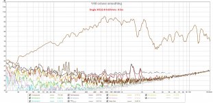
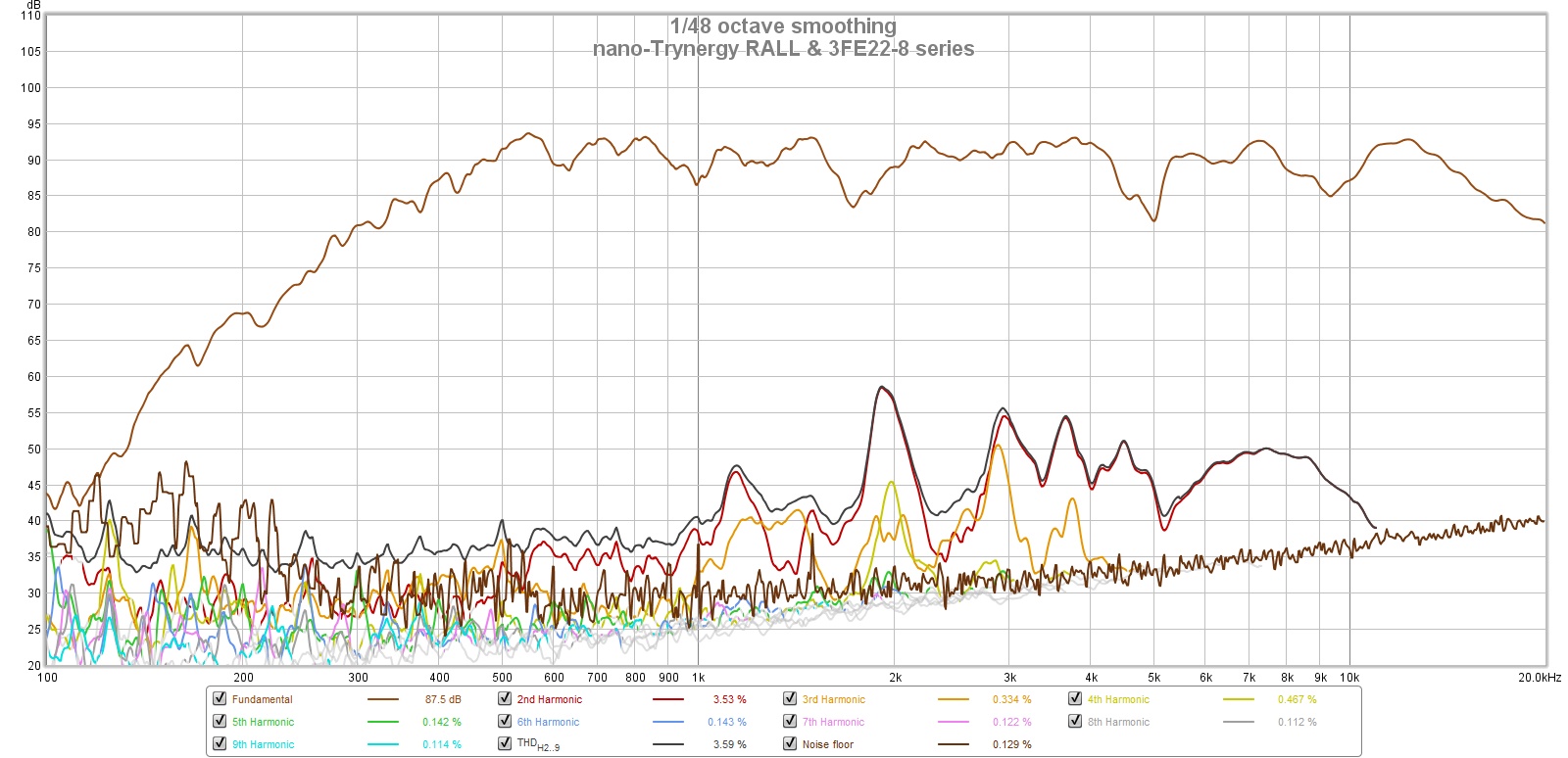
Here is the THD vs frequency for the RAAL running at 0.63Vrms, also showing very low distortion levels. This is equivalent to about 95dB at 2.83v and 1m. The 3FE22's could also be wired in series for 16ohms and that would help to match the sensitivities better and still keep a larger dynamic range and lower distortion:
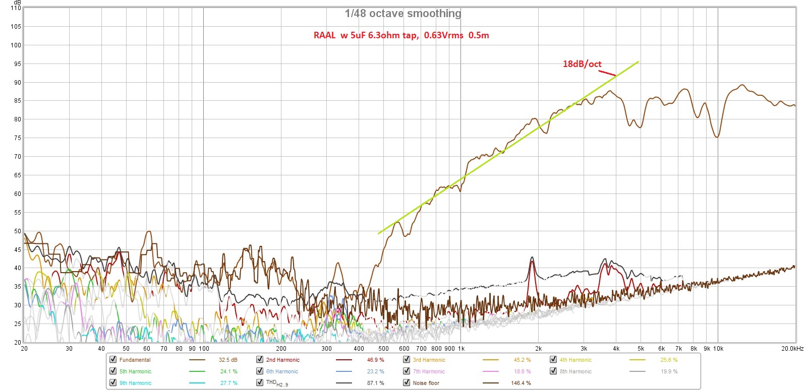
Of interest is the acoustic slope of -18dB/oct on the high pass filter function. This could be very useful for a Harsch XO.
Next steps are to see if the nagging dips at 4.7khz and 10khz can be reduced or eliminated. I think they are wall reflections in the vertical (4.7kz) and horizonatal (10kHz) from the ribbon membrane to the horn side walls.
This will be interesting but certainly shows there is lots of work to be done, but there is promise here for a very compact point source horn. I will try to do some basic EQ and DSP crossover on the mid range. Let the RAAL run via passive high pass but maybe apply some EQ (cuts only, no boost). Will try maybe a 1.7kHz crossover to take advantage of the natural dip there.
The horn dimensions are about the size of a sheet of letter paper (8.5in high x 11in wide x 7.5in deep). The envisioned frequency range is 500Hz to 20kHz+ with a crossover from 1.8kHz to 2.6khz. Integration with an externa woofer will provide bass below 500Hz.
The midrange will be handled by dual Faital Pro 3FE22 (8ohms) wired in parallel. However, I have found that this combo produces almost too much sensitivity. At 2.0Vrms and 0.5m, the microphone was clipping and my ears were ringing. I think the peak sensitivity was probably about 105dB at 2.83v. As a result, I had to back off the excitation to about 0.63Vrms to keep things bearable for measurements. An observation, consistent with my earlier efforts to use an AMT for a Synergy style horn was that there is very little horn-gain for the tweeter. Maybe 2dB... I think this results from the very small low mass diaphragm that does not pistonically "pump" the air column at the throat vs. a dynamic driver that acts more as a piston and hence experiences typically 10dB of horn gain.
Here is the completed protoype Trynergy horn made out of Elmer's thick paper-faced foam core material. I tried the glossy finish foam core (vs matte) and although it looks great, the hot melt glue does not adhere well as the surface is glossy via a wax coat treatment. If I did it all over again, I would use the matte finish.
Rear view of the prototype showing open back stuffed with fiberglass in a manner similar to the microTrynergy. This provides enough of an enclosure to allow the mid range to go down to 500Hz with a -12dB/oct falloff. This is exactly where I wanted the crossover to be, so it worked out well. The bass drivers can be anything, but a pair of nice 8in woofers in open face saeled or reflex or TL etc can take this from 500Hz down to circa 50Hz easily. A set of woofers above and below for a WHW (woofer-horn-woofer) arrangemennt might work out real well for a point source system. The horn is surprisngly rigid once all glued together. The two top and bottom driver moutning plates serve large rib reinforcemnts to make the box quite stiff, yet surprisngly light weight.
Here are the construction details showing the liberal use of Noico mass-loaded butyl for resonance reduction. The panels and especially the horn walls are very dead sounding under the 'knuckle rapping' test. This will be evident in the very low THD vs frequency plots:
Noico on the side panels as well:
Lot's of pink fiberglass sound dampening is used throughout, some felt right behind the driver magents, and some use of melamine foam at strategic locations:
Here is a closeup of the throat and mid-range injection ports (20mm x 40mm at 23mm from throat plane). Throat is approx 40mm wide x 70mm tall. The location was made as close as physically possible given the bezel diameter of the 3FE22:
Getting measurements made using UMIK-1 at 0.5m to avoid room reflections:
Measured response with freq dependent window (FDW) 6 cycles for mids and ribbon at various excitation levels and impedance taps:
The mid range has a sharp dip at 1.74khz, which I believe corresponds to the reflection cancellation from the top and bottom walls at the throat injection point (3.8in). The goal was to get up to 3kHz if possible.
Here is the THD vs frequency of one 3FE22 running at only 0.63Vrms - about 87dB at 1m ( a very comfortable SPL) and showing very low levels of distortion. Panel resonances look well controlled despite 3/16in thick foam core construction:
Here is the THD vs frequency for the RAAL running at 0.63Vrms, also showing very low distortion levels. This is equivalent to about 95dB at 2.83v and 1m. The 3FE22's could also be wired in series for 16ohms and that would help to match the sensitivities better and still keep a larger dynamic range and lower distortion:
Of interest is the acoustic slope of -18dB/oct on the high pass filter function. This could be very useful for a Harsch XO.
Next steps are to see if the nagging dips at 4.7khz and 10khz can be reduced or eliminated. I think they are wall reflections in the vertical (4.7kz) and horizonatal (10kHz) from the ribbon membrane to the horn side walls.
This will be interesting but certainly shows there is lots of work to be done, but there is promise here for a very compact point source horn. I will try to do some basic EQ and DSP crossover on the mid range. Let the RAAL run via passive high pass but maybe apply some EQ (cuts only, no boost). Will try maybe a 1.7kHz crossover to take advantage of the natural dip there.
Attachments
-
 nano-Trynergy-RAAL-photo-01.jpg497.3 KB · Views: 7,990
 -
 RAAL-Trynergy-0.5m-Meas-60hm-THD-plot-10.jpg281 KB · Views: 4,704
 -
 RAAL-Trynergy-0.5m-Meas-8ohm-3FE22-plot-09.jpg295.3 KB · Views: 1,725
 -
 RAAL-Trynergy-0.5m-Measure-plot-08.jpg258.3 KB · Views: 2,854
 -
 nano-Trynergy-RAAL-photo-07.jpg203.8 KB · Views: 1,811
 -
 nano-Trynergy-RAAL-photo-06.jpg162.6 KB · Views: 5,854
 -
 nano-Trynergy-RAAL-photo-05.jpg297.1 KB · Views: 1,773
 -
 nano-Trynergy-RAAL-photo-04.jpg479.7 KB · Views: 1,778
 -
 nano-Trynergy-RAAL-photo-03.jpg366.1 KB · Views: 3,373
 -
 nano-Trynergy-RAAL-photo-02.jpg472.4 KB · Views: 2,558
Last edited:
Interesting. I can't help wondering whether the pressure created by the midrange drivers would move the ribbon outside of its ideal operating limits.
That’s a good question. I was actually worried that the pressure might even damage the foil membrane. However, if we make sure we high pass the mids above 500Hz, I don’t think that these will be the deep impulsive pressure waves like those from a kick drum. I will shine a light on the membrane and try to observe the deflection.
I really
Like your build. Do you or would you share the cut sheet and build plans? If no I understand,
Like your build. Do you or would you share the cut sheet and build plans? If no I understand,
Here are the PDF plans for the horn walls in full scale for a 5in dynamic driver (30in wide horn mouth). I scaled the drawings by about 33% and I also added translations of the profiles to enlarge the throat to a rectangle that fits the ribbon aperture. You just have to manually print a few times on your printer, measure and adjust. It took me about print 4 tries to get it right. Make sure you test out the curved wall along the wall interface line to make sure they are the same size. The rest of the build is all manual cut and measure by eye - no cut sheet. Basically, build the rest of the box around the main horn.
So use the curved profiles by cutting them out to use as a stencil to trace a line onto the foamcore. Flip the template to mirror it along the centerline and move it over to make the height/width of the aperture consistent. For the flat panel lines where the curved sidewalls need to bend before gluing, do the same thing.
So use the curved profiles by cutting them out to use as a stencil to trace a line onto the foamcore. Flip the template to mirror it along the centerline and move it over to make the height/width of the aperture consistent. For the flat panel lines where the curved sidewalls need to bend before gluing, do the same thing.
Attachments
Last edited:
Super interesting!!
What's your opinion about using a Beyma TPL-150 instead?
I have TPLs, and been toying with the idea of a TPL, maybe 4x 3FE22 (or 25) but in an array, and two 10" for midbass. So I'm very interested.
What's your opinion about using a Beyma TPL-150 instead?
I have TPLs, and been toying with the idea of a TPL, maybe 4x 3FE22 (or 25) but in an array, and two 10" for midbass. So I'm very interested.
The TPL-150 works very well in a synergy with an 8in woofer like SB23. I have seen it done very well. Cross over at about 1kHz.
This used TPL & 2 JBL 2251J 10" on the sides open baffle, took me about a hour to make it.
Crossover was 1khz, the large horn loads the TPL down low very well.
Great!
Did you have a thread to that build? So to not distract in this thread. I guess your xo is lower than 500Hz given the horn size.
I did a similar thing with the Heil AMT in a Synergy and B&C 6MDN44. It sounds fantastic.
It was a private design but there is some more info here:
ESS AMT-1 in my projects
It was a private design but there is some more info here:
ESS AMT-1 in my projects
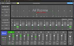
Here is a quick and dirty DSP XO that I set up to see how it sounds. I used the Dayton DSP-408 and a basic -18dB/oct slope at 300Hz HPF and 2200Hz -24dB/oct slope LPF for the dual 3FE22-8's wired in series. Had to apply -8.7dB attenuation on midranges to level match with the RAAL tweeter since the horn gain is so effective for the dynamic drivers. The RAAL is just straight pass through on the DSP, but with -0.42ms delay in one case. Without the delay, this would be a simple passive crossvover on the 3FE22's as no EQ was applied anywhere. I added a bunch of melamine reticulated foam pads around the throat and midrange injection ports. It smoothed the top end of the RAAL quite a bit, but too away a little bit of top end response. It did nothing for the midrange dip at 1.7kHz though. This seems to indicate that the utmost care has to be given to designing smooth gradual transisition from the RAAL faceplate to match the horn throat. This has to be done using a 3D print and may still require some foam. But the addition of the oam shows that the dips are reflection induced.
Here are the DSP settings:

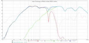
Here is a plot of the measured woofer and tweeter plus combined system. Two cases with and without delay are shown:
I verified that the phase alignment was quite good as deep cancellation peaks were present when the polarity of the tweeter was flipped.
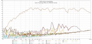
However, at higher SPL's, there seems to be some bad high distortion peaks on the RAAL - I am sure this is caused by putting the RAAL in this horn as they are supposed to be very low distortion devices when used conventionally on a flat baffle. I suspect this might be caused by the lack of butyl famping on the thin wall in front of the mid range drivers. I will need to measure the RAAL all by itself on a flat baffle to characterize the baseline:
There is obvioulsy a lot of work to be done to smooth this out and it has mostly to do with smoothing out the reflection dips near the horn throat. But, one good thing is that no notch filtering or EQ was needed - just simple 3rd and 4th order filters and attenuation was required on the mid ranges. Nothing needed to be done electrically on the RAAL except adding a 5uF cap in series.
I need to add some 8in RS225 8ohm woofers in sealed cabinets above and below and see how it sounds. Right now it sounds tinny since only stuff above 500Hz is present. Sort of like listening to a a big softdome or maybe a Heil AMT all by itself.
Here are the DSP settings:
Here is a plot of the measured woofer and tweeter plus combined system. Two cases with and without delay are shown:
I verified that the phase alignment was quite good as deep cancellation peaks were present when the polarity of the tweeter was flipped.
However, at higher SPL's, there seems to be some bad high distortion peaks on the RAAL - I am sure this is caused by putting the RAAL in this horn as they are supposed to be very low distortion devices when used conventionally on a flat baffle. I suspect this might be caused by the lack of butyl famping on the thin wall in front of the mid range drivers. I will need to measure the RAAL all by itself on a flat baffle to characterize the baseline:
There is obvioulsy a lot of work to be done to smooth this out and it has mostly to do with smoothing out the reflection dips near the horn throat. But, one good thing is that no notch filtering or EQ was needed - just simple 3rd and 4th order filters and attenuation was required on the mid ranges. Nothing needed to be done electrically on the RAAL except adding a 5uF cap in series.
I need to add some 8in RS225 8ohm woofers in sealed cabinets above and below and see how it sounds. Right now it sounds tinny since only stuff above 500Hz is present. Sort of like listening to a a big softdome or maybe a Heil AMT all by itself.
Attachments

Last edited:
Nice! The 3FE22s seem to work fine, I plan to use them for my AMT Synergy so that I have more freedom with the crossover point.
Very nice!
That's a big horn, though. 45x30 deg and 30in wide, right?
Too large for my WAF. Can probably go up to 18-20" wide. What's your opinion about an 18" wide tractrix with TPL + midranges?
That's a big horn, though. 45x30 deg and 30in wide, right?
Too large for my WAF. Can probably go up to 18-20" wide. What's your opinion about an 18" wide tractrix with TPL + midranges?
I put the mid ports as close as I could to avoid that. The center of the ports are 23mm from the RAAL faceplate. The ribbon is another 10mm behind that. Maybe that’s what it is though. I could remove the RAAL and take a sweep to see if it goes away. I sort of dismantled the test gear though to do some lab cleanup.
Very nice!
That's a big horn, though. 45x30 deg and 30in wide, right?
Too large for my WAF. Can probably go up to 18-20" wide. What's your opinion about an 18" wide tractrix with TPL + midranges?
I have seen smaller ones with a TPL. Maybe 20in wide 90deg.
I have seen smaller ones with a TPL. Maybe 20in wide 90deg.
20in wide & 90deg tractrix or double expansion?
- Home
- Loudspeakers
- Multi-Way
- Nano-Trynergy - a Compact Tractrix RAAL Ribbon Point-Source Horn