This is in isolation. If it were inserted into a broadband flat response where this amount were exactly missing (the resonance is filling a response dip), could things be different?
This is in isolation. If it were inserted into a broadband flat response where this amount were exactly missing (the resonance is filling a response dip), could things be different?
Ringing is ringing Allen... it's not coming from the amplifier but it is going out the speaker ... that makes it distortion.
In case you didn't notice, the input pulse, which has the same width as the ring frequency does not make it to the speaker...
Last edited:
@Douglas Blake,
Even if some of the discussions in last few posts are over my head somewhat I am still following along and enjoying the depth of these discussions. Thanks a million!😀
Best Regards,
Rich
Even if some of the discussions in last few posts are over my head somewhat I am still following along and enjoying the depth of these discussions. Thanks a million!😀
Best Regards,
Rich
Interesting Douglas. Thanks for that.
And because I just can't help myself sometimes.....
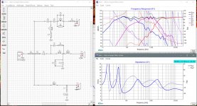
Rich, here's another attempt trying to keep the FR, phase etc as good as possible but also trying to improve efficiency and avoid as much ringing as possible. Just adding a cap to the RL combo turns it into a wide shallow notch filter centered at about 10kHz and totally changes the power consumption on that parallel resistor R3. No more ringing I think. I also like the fact that the tweeter now needs some series resistance - that gives you a little more flexibility in terms of fine tuning its level to taste.
I still was a little worried about that peak resonance on the mid at 4kHz so I added a notch back in with the cap/resistor combo over L2. Went down to 3rd order electrical on the mid too. Not quite as smooth but good enough I think.
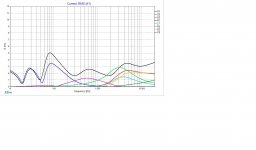
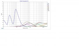
More efficient too this time. The only problem I can identify is on the tweeter shunt due to the small inductor L3, green trace on the current chart which exceeds the current draw for the whole system between about 1600 and 3000Hz. That would be some more ringing I guess. But only a tiny little bit this time. I think. 😀
Dxo is attached. Do with it as you will.
And because I just can't help myself sometimes.....
Rich, here's another attempt trying to keep the FR, phase etc as good as possible but also trying to improve efficiency and avoid as much ringing as possible. Just adding a cap to the RL combo turns it into a wide shallow notch filter centered at about 10kHz and totally changes the power consumption on that parallel resistor R3. No more ringing I think. I also like the fact that the tweeter now needs some series resistance - that gives you a little more flexibility in terms of fine tuning its level to taste.
I still was a little worried about that peak resonance on the mid at 4kHz so I added a notch back in with the cap/resistor combo over L2. Went down to 3rd order electrical on the mid too. Not quite as smooth but good enough I think.
More efficient too this time. The only problem I can identify is on the tweeter shunt due to the small inductor L3, green trace on the current chart which exceeds the current draw for the whole system between about 1600 and 3000Hz. That would be some more ringing I guess. But only a tiny little bit this time. I think. 😀
Dxo is attached. Do with it as you will.
Attachments
filter ringing is that akin to the onset of feedback in an open mike situation?
No... it's more like what you get after you strike a bell... and it just keeps on going.
All filters ring to some degree, the question is how much.
Last edited:
that impedance curve looks scary!!!
is it just me...
No it looks fairly normal to me. Stays above 4ohm everywhere.
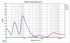
Part of the reason for this thread though is to take a closer look at some of the other stuff XSim can tell us. In particular the current consumption and how wasteful it can be as well as what's happening in terms of power draw by each driver and different components. Both of those charts tell me that things are looking pretty good (though I'd like to have Douglas confirm that for me). But it will need some power though if you want to play it up to the very high SPL levels the speaker is capable of.
Both of those charts tell me that things are looking pretty good (though I'd like to have Douglas confirm that for me).
Okay ... edit time...
Yeah it looks pretty good. More complex than I would like but those are some seriously gnarly drivers.
Other than a click or two here and there on part values... I'd say go for it.
Can we do an easy one next time???
Last edited:
Okay ... edit time...
Yeah it looks pretty good. More complex than I would like but those are some seriously gnarly drivers.
Other than a click or two here and there on part values... I'd say go for it.
If you decrease both R2 and C1, you might be able to trim that current peak a bit without messing up the response.
Can we do an easy one next time???
Okay ... that was seriously weird...
Thanks jReave,
I like that version a lot.😀 That one should do the trick. One thing we can agree upon is these drivers were difficult to tame. If I could have a mulligan on this( if I can throw out a golf analogy) my choice of drivers would be different. This entire thread has been a very interesting journey to say the least! I’m glad that for my next build I purchased Satori drivers for mid and tweet with SB Acoustics 12in woofer. These all appear to be incredibly smooth in their frequency response. Thus crossover design should be much easier.😀 Thanks for everything!
Best Regards,
Rich
Thanks jReave,
One thing we can agree upon is these drivers were difficult to tame.
Gees, ya think?? 😀
Gald you got it sorted ... be sure to let us know how it works out for you.
that impedance curve looks scary!!!
is it just me...
Naaa ... young fella thinks he's designing roller coasters...
It's no problem as long as the impedance stays at or above the driver spec.
@Douglas Blake,
I will be sure to post into this thread once I get these filters built and installed. It looks like at first glance I already have most everything from jReave’s latest design so I should not need much of a purchase from Parts Express. This has been incredibly fun exercise!😀 Maybe there will be more discussions on this thread to follow. There could possibly be someone else that has a tougher nut to crack then the project I submitted.😀 Anyways, Douglas I really enjoy reading your posts!
Take Care and Be Safe,
Rich
@Douglas Blake,
I will be sure to post into this thread once I get these filters built and installed.
Now the bad news 😉 For the most part these simulations will get you pretty close. But you shouldn't consider them as final designs. You may sill have to tinker with a part value here and there in the real device to get it right. Right now you are "pretty darned close" but I would not count on perfection.
There could possibly be someone else that has a tougher nut to crack then the project I submitted.😀
Noooooooooo!
Anyways, Douglas I really enjoy reading your posts!
Take Care and Be Safe,
Rich
You too my new friend ... happy music.
Always room for improvement. I was wondering if maybe we could decrease the current and wattage usage down around 100Hz which is what Douglas was suggesting I think in post #110.
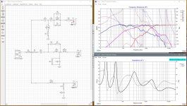
So I dropped the woofer shunt capacitor and the mid series capacitor values and raised the woofer series inductor. I think this is actually closer to one of your ealier sims Rich. That saves about 1 amp of current loss and almost 10W of power consumption in that LF area. Impedance minimum there is now up to about 5ohm too.
I adjusted a couple of resistor values as well here and there to try to give a better balance, maybe with a tiny bit of extra bass presence. But that's going to be totally up to you Rich, and as Douglas suggests you are still going to want to fine tune it by ear. At least now you have resistors in line with both the mid and the tweeter so it becomes a little easier to make those smaller adjustments to the bass, mid and treble ranges.
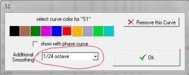
Note I switched the FR Graph's scale so that the FR looks a little smoother. This a way to visually reinforce something Douglas was saying in terms of us not really hearing the smaller peaks and valleys. I think it was Jeff Bagby who said that we actually hear closer to 1/6th octave smoothing so I think this is closer to what your ears will hear. If you adjust the scale again to 3dB increments, you can see that your FR is actually +/- 1.5dB except for the slight peak at 70Hz. Pretty darn good when +/- 3dB is kind of the industry standard.
Also note that I haven't bothered to pay attention to any of the inductors' resistance values. Along with looking at the wattage maximums for all the resistors (I think R2 on the mid might see some higher potential power still) and checking that all the component values are available in the real world, getting the right R values for the inductors is one of the last things I do in a sim. You may find that other values can be adjusted to compensate. Just for eg, with L3, the tweeter shunt inductor, you can choose a very narrow gauge wire which will have a higher R value and will be less expensive and then subtract that from R5, the resistor in series with it or perhaps not even need that resistor at all if the inductor R value is up near 1.5 - 2ohm.
Happy listening indeed.
So I dropped the woofer shunt capacitor and the mid series capacitor values and raised the woofer series inductor. I think this is actually closer to one of your ealier sims Rich. That saves about 1 amp of current loss and almost 10W of power consumption in that LF area. Impedance minimum there is now up to about 5ohm too.
I adjusted a couple of resistor values as well here and there to try to give a better balance, maybe with a tiny bit of extra bass presence. But that's going to be totally up to you Rich, and as Douglas suggests you are still going to want to fine tune it by ear. At least now you have resistors in line with both the mid and the tweeter so it becomes a little easier to make those smaller adjustments to the bass, mid and treble ranges.
Note I switched the FR Graph's scale so that the FR looks a little smoother. This a way to visually reinforce something Douglas was saying in terms of us not really hearing the smaller peaks and valleys. I think it was Jeff Bagby who said that we actually hear closer to 1/6th octave smoothing so I think this is closer to what your ears will hear. If you adjust the scale again to 3dB increments, you can see that your FR is actually +/- 1.5dB except for the slight peak at 70Hz. Pretty darn good when +/- 3dB is kind of the industry standard.
Also note that I haven't bothered to pay attention to any of the inductors' resistance values. Along with looking at the wattage maximums for all the resistors (I think R2 on the mid might see some higher potential power still) and checking that all the component values are available in the real world, getting the right R values for the inductors is one of the last things I do in a sim. You may find that other values can be adjusted to compensate. Just for eg, with L3, the tweeter shunt inductor, you can choose a very narrow gauge wire which will have a higher R value and will be less expensive and then subtract that from R5, the resistor in series with it or perhaps not even need that resistor at all if the inductor R value is up near 1.5 - 2ohm.
Happy listening indeed.
Attachments

So I dropped the woofer shunt capacitor and the mid series capacitor values and raised the woofer series inductor. I think this is actually closer to one of your ealier sims Rich. That saves about 1 amp of current loss and almost 10W of power consumption in that LF area. Impedance minimum there is now up to about 5ohm too.
Nice...
Note I switched the FR Graph's scale so that the FR looks a little smoother. This a way to visually reinforce something Douglas was saying in terms of us not really hearing the smaller peaks and valleys. I think it was Jeff Bagby who said that we actually hear closer to 1/6th octave smoothing so I think this is closer to what your ears will hear.
Actually you can set that in the Curve dialog when opening a new SPL curve.
See the thumbnail. When I work I usually use 1/12 octave smoothing because that pretty much corresponds with the musical scale of 12 notes per octave... But to get a look at averages instead of instantaneous values, even 1/3 octave smoothing is helpful. Also note there is a curve selection for "Auditory ERB" in there that allows you to pretty much see what you would hear, taking the ear into account. Setting a smoothing factor on the System trace, sets all the others too.
Attachments
Last edited:
@jReave,
Thank you so very much for your latest design iteration! I Really like it.😀 This one allows me to make use of large value components in the woofer filter that I already have in inventory. 🙂 Thanks a million for all your time and effort on this project!!!
@Douglas Blake
Thanks for pointing out those additional settings.😀
You Both Have A Great Day!
- Home
- Loudspeakers
- Multi-Way
- Xsim Critique- taking it to the next level